
PORTABLE SPEECH-TO-TEXT
DISPLAY SYSTEM
By
Anthony Dust
John Ryan Hamilton
Final Report for ECE 445, Senior Design, Spring 2017
TA: Yuchen He
03, May 2017
Project No. 50
ii
Abstract
We designed a portable device that converts speech to text and displays it on an LCD screen. We
designed and constructed a bandpass filter to filter audio within human voice ranges, then processed
the audio data in a microcontroller with software to convert the data to text. The microcontroller then
outputs the text to an LCD screen for display. We verified that all components of our design met our
requirements, but were unable to integrate the LCD display with the rest of the circuit.
iii
Contents
1. Introduction .............................................................................................................................................. 1
1.1 Objectives...................................................................................................................................... 1
1.2 Design ............................................................................................................................................ 1
1.2.1 Design Changes ..................................................................................................................... 2
2. Design Procedure ...................................................................................................................................... 3
2.1 Power Supply ...................................................................................................................................... 3
2.1.1 9 Volt Battery Bank ...................................................................................................................... 3
2.1.2 5 Volt Voltage Regulators ............................................................................................................ 3
2.2 Input System ....................................................................................................................................... 3
2.2.1 Microphone .................................................................................................................................. 3
2.2.2 Bandpass Filter ............................................................................................................................. 3
2.2.3 Soundcard .................................................................................................................................... 4
2.3 Control System .................................................................................................................................... 4
2.3.1 Microcontroller ............................................................................................................................ 4
2.3.2 SD Card ......................................................................................................................................... 4
2.3.3 Software ....................................................................................................................................... 4
2.4 Output System .................................................................................................................................... 5
2.4.1 LCD Display ................................................................................................................................... 5
3. Design Details ............................................................................................................................................ 6
3.1 Power Supply ...................................................................................................................................... 6
3.1.1 9 Volt Battery Bank ...................................................................................................................... 6
3.1.2 5 Volt Voltage Regulators ............................................................................................................ 6
3.2 Input System ....................................................................................................................................... 6
3.2.1 Microphone .................................................................................................................................. 6
3.2.2 Bandpass Filter ............................................................................................................................. 7
3.2.3 Soundcard .................................................................................................................................... 8
3.3 Control System .................................................................................................................................... 8
3.3.1 Microcontroller ............................................................................................................................ 8
3.3.2 SD Card ......................................................................................................................................... 8
iv
3.3.3 Software ....................................................................................................................................... 8
3.4 Output System .................................................................................................................................... 9
3.4.1 LCD Display ................................................................................................................................... 9
4. Design Verification .................................................................................................................................. 10
4.1 Power system .................................................................................................................................... 10
4.1.1 9V Battery Bank.......................................................................................................................... 10
4.1.2 5V Voltage Regulators ................................................................................................................ 11
4.2 Input System ..................................................................................................................................... 12
4.2.1 Microphone ................................................................................................................................ 12
4.2.2 Bandpass Filter ........................................................................................................................... 13
4.2.3 Soundcard .................................................................................................................................. 14
4.3 Control System .................................................................................................................................. 14
4.3.1 Microcontroller .......................................................................................................................... 14
4.3.2 SD Card ....................................................................................................................................... 14
4.3.3 Software ..................................................................................................................................... 14
4.4 Output System .................................................................................................................................. 15
4.4.1 LCD Screen ................................................................................................................................. 15
5. Costs ........................................................................................................................................................ 16
5.1 Parts .................................................................................................................................................. 16
5.2 Labor ................................................................................................................................................. 16
6. Conclusion ............................................................................................................................................... 17
6.1 Accomplishments .............................................................................................................................. 17
6.2 Uncertainties/Challenges .................................................................................................................. 17
6.3 Ethical considerations ....................................................................................................................... 17
6.4 Future work ....................................................................................................................................... 17
References .................................................................................................................................................. 19
Appendix A Requirement and Verification Table ................................................................................... 20
1
1. Introduction
1.1 Objectives
According to the World Health Organization, over 5% of the world’s population suffers from disabling
hearing loss[1]. Current hearing impaired communication methods are rudimentary at best. Medical
centers advise things such as speaking slowly and clearly, face the hearing impaired individual directly,
and minimize extra noises[2]. Even the U.S. department of justice advises use of a pad and pencil, sign
language interpreter, or specialized teletypewriter[3], for important communication to hearing impaired
individuals. Even in important situations like law enforcement and medical practice, communication
methods with the deaf are severely lacking. Our project has the capability to revolutionize easy and
practical communication with these people with a convenient and portable system capable of
converting a user’s speech to text on a display.
1.2 Design
Our project design requires four main systems for successful operation (shown in Figure 1.1 below): a
power supply, an input system, a control system, and an output system. The power supply powers the
microcontroller, bandpass filter, microphone, and LCD display for over 30 minutes of on time. The
power supply also contains two voltage regulators, to ensure that the 5 volts required are reaching the
proper systems. The input system consists of a microphone able to detect normal human speech, a
bandpass filter to filter out extraneous noise in the vocal frequency range, and a soundcard to convert
the analog signal to digital, cleanly sample it at high frequencies, and provide a driver to interact with
the microcontroller. The control system consists of microcontroller utilizing a speech-to-text program to
translate the audio data into text and output it to the output system, as well as an SD card to hold the
program’s data. The output system consists of an LCD screen that displays the text sent to it from the
microcontroller.

2
Figure 1.1 Block Diagram
1.2.1 Design Changes
Our design went through several changes throughout the course of the semester. Initially the output
system consisted of several LED matrices and LED drivers to control the outputs. This idea was scrapped
due to the large power demands of LED matrices, as well as the constraint on number of available
characters. Additionally, the bandpass filter originally sent data directly to the microcontroller. Due to
the lack of analog inputs on the Raspberry Pi, our microcontroller, we had to convert the analog signal
into a digital one, so an analog-to-digital converter (ADC) was implemented. This later changed into a
soundcard after we realized the other factors necessary for audio conversion to the Raspberry Pi, such
as analog to digital conversion, clean high frequency sampling, as well as a device driver.
3
2. Design Procedure
2.1 Power Supply
2.1.1 9 Volt Battery Bank
We selected the 9 volt battery bank to power all blocks in the design. All of the blocks requiring power
needed 5 volts to function, so we needed a high enough voltage that it could be regulated to 5 easily
without overheating the regulators. We selected 6 1.5V alkaline batteries in series due to an earlier
design idea of using 7.5 volts (5 batteries) to run the circuit. After testing this idea, we determined that 6
batteries was the more consistent way to power the voltage regulators. Alternatively, at this stage, a
simple 9 volt battery could also be implemented instead of the 6 battery bank.
2.1.2 5 Volt Voltage Regulators
As previously discussed, our project required 5 volts to operate all systems, so we selected 5 volt voltage
regulators to power the circuit. In order to keep the voltage as steady as possible, we used voltage
regulator chips. Alternative designs involved constructing our own voltage regulators, but was deemed
too unsafe with fragile components like the Raspberry Pi connected to power. In order to ensure safety
of both the components of the circuit as well as the user, we used UA7805 voltage regulators.
2.2 Input System
2.2.1 Microphone
We selected a microphone that met the requirements of our audio conversion system: reading audio
between 300Hz and 3kHz and outputting the audio signal with little to no frequency loss. Because of
this, we selected an Electret microphone with a built-in preamp. Alternate designs involved using a USB
microphone. While this idea greatly simplifies the steps necessary to construct the project, it also
eliminated a large amount of our design complexity in the bandpass filter, and was not implemented
due to complexity considerations.
2.2.2 Bandpass Filter
The bandpass filter was one of the more complex choices we faced in our design. We initially decided on
using an active filter, as active filters were far more precise for the audio filtering necessary. We then
had to decide between Butterworth and Chebyshev filter designs. The upside of Butterworth filters are
that they are much flatter than other filters between the cutoff frequencies. The tradeoff is that
Chebyshev filters have a much more precise falloff past the cutoff frequencies. The other consideration
was the order of the active filter. Additional orders make the filter more precise at the cost of increasing
complexity and size of the filter. We selected a 3
rd
order Butterworth filter after assessing our desire for
a more uniform bandpass region, using a 3
rd
order filter for more precise falloffs around the cutoff
frequencies.
4
2.2.3 Soundcard
Originally we used an ADC to convert the microphone’s analog input to a digital signal for input to the
microcontroller’s digital input pins. Due to time constraints and integration concerns, we were not able
to create any type of driver for the ADC to work with our microcontroller, even with jitter, so we
researched soundcards. There are two market competitors, however one has been sold out and likely
discontinued, and the other just broke into the market earlier this year with a successful funding on
kickstarter. Despite having little documentation, we gave this soundcard a shot and it worked out, albeit
with some extra challenges. Without this soundcard, we would not have been able to integrate the
input system with the control system by the deadline. Additionally, this soundcard was not well
documented for our use with our software choice pocketsphinx. Because of this we had to adapt an
open source python script, which utilized PyAudio, jackd, and pulseaudio to interface the soundcard
with the microcontroller. We utilized a volume threshold for voice activity detection and called our bash
speech recognition script from our speech recognition python script detailed in the software section.
2.3 Control System
2.3.1 Microcontroller
We selected the Raspberry Pi 3B as our microcontroller of choice. After looking through the speech-to-
text software information, we found a software test run on the Pi 3 and Pi B+. The Pi 3 had
approximately 0% word error rate (WER), while the B+ had around 37% for the more complex tests. In
addition, the Pi 3 was shown to be 3.72 times faster than the B+, indicating that to operate in more real
time, we wanted better processing ability. If processing speed were not an issue and a large enough SD
card were used, we could have possibly scaled the microcontroller back to a less complex Pi, but in order
to safely meet design requirements, we selected the Pi 3B.
2.3.2 SD Card
We selected an SD card that fulfilled our design requirements of being able to store our language model,
operating system, and speech-to-text software (approximately 1 GB). Other design considerations
involved use of a flash drive, which would speed up the read and write times, but in testing our SD card,
we found the times to fall within our requirements.
2.3.3 Software
The original software design used CMU’s pocketsphinx in order to convert speech to text. This allowed
for a portable system requiring no wireless radios that could be used anywhere. There were also several
tutorials online documenting the use of pocketsphinx with our microcontroller. However, every tutorial
detailed the process for using pocketsphinx with USB microphones. This was a challenge, because there
were no resources for using pocketsphinx with our soundcard. Again, due to time constraints, it wasn’t
possible to reverse engineer the soundcard and pocketsphinx in order to debug our issues. So instead,
we chose to look into cloud APIs as pocketsphinx was the only viable option for a self-contained system.
With a cloud API we would be able to integrate the input system with the microcontroller. We looked
into Amazon, Google, and Bing’s speech APIs. We chose Bing’s API because it was well documented and
included documentation for making requests with the curl utility. Coupled with our python voice activity
detection script, we were able to successfully convert speech to text.
5
2.4 Output System
2.4.1 LCD Display
We selected an output system that was both convenient to write to and read from, and had low power
consumption to aid in the portability of the project. To fulfill these design requirements we selected an
LCD display screen. Our initial design used LED matrices to light up in specific characters, but the idea
limited character number and greatly increased power consumption. By implementing an LCD display
instead, we allowed for 32 characters (with scrolling available for longer sentences) as well as a large
reduction in power consumption.

6
3. Design Details
3.1 Power Supply
3.1.1 9 Volt Battery Bank
Our battery bank consists of a pack of 6 series AA batteries.
3.1.2 5 Volt Voltage Regulators
The UA7805 voltage regulators[4] we selected have a minimum operating voltage of 7 volts, meaning if
supplied with 7 or more volts, the regulator will output a clean 5 volts. We also connected capacitors in
parallel to the input and output of the regulator, shown in figure 3.1. Their function is to draw any AC
voltage going into or out of the regulator to provide a more stable voltage.
Figure 3.1 Voltage Regulator Circuit[4]
3.2 Input System
3.2.1 Microphone
We selected an electret microphone[5] with built-in preamp[6] to properly capture the audio data. The
frequency detection range is 100Hz to 10kHz, so this falls well within the desired cutoffs implemented
by the filter. A mockup of the microphone design is shown in figure 3.2. The microphone simply requires
an input voltage of 2.7-5.5V and a ground, and will output the analog audio signal through the AUD
channel.
Figure 3.2 Microphone Design Mockup

7
3.2.2 Bandpass Filter
The bandpass filter we selected is a 3
rd
order Butterworth bandpass filter, created by cascading a
highpass filter into a lowpass filter. The basic design of the filters are shown in figure 3.3 and 3.4, and
show the values we used to calculate proper cutoff frequencies. Equations 1 and 2 demonstrate the
calculations for cutoff frequencies of high and low pass butterworth filters, respectively.
(Eq. 1)
(Eq. 2)
Figure 3.3 3
rd
Order Butterworth Highpass Filter
Figure 3.4 3
rd
Order Butterworth Lowpass Filter
8
3.2.3 Soundcard
The soundcard has an onboard analog to digital converter, a sample rate of 96 kHz, a sample size of 32
bits, and a device driver already included in Raspbian. The specifications allowed us to convert the
analog signal to digital, sample at high frequencies with minimal jitter, and provide that input as a
system device to our speech recognition software.
3.3 Control System
3.3.1 Microcontroller
We selected the Raspberry Pi 3B as our microcontroller. The processing power of the 3B allowed for
more real time speech-to-text conversion, as well as a word error rate of close to 0%[9]. The downside
of the more powerful microcontroller is that it consumes more power, being the largest power sink in
our system at approximately .4A[7], consuming an average power of 2W while turned on.
3.3.2 SD Card
The SD card selected had at least 1GB of space to store the language model, operating system
(Raspbian), and the speech-to-text conversion program. It also needed to meet our microcontroller
communication speed in order to fulfill the conversion time of 2 seconds to keep the system in real time.
3.3.3 Software
The software consists of two bash scripts and a python wrapper script. The python wrapper scripts
detects voice activity at a pre-defined volume threshold in a loop. When the volume dips below the
threshold, the software cuts a .wav file, saves it to disk, and calls the speech recognition bash script. If it
has been 9 minutes since the last authentication token was generated, a new token is generated. The
script makes a web request to the Bing Speech API and retrieves a result. The result is parsed for the
output text, and the output text is displayed on the LCD screen. Finally, the script deletes the .wav file.

9
3.4 Output System
3.4.1 LCD Display
The LCD display screen is a 32 character (16x2) screen measuring 1.4” by 3.2”, as seen in figure 3.5. The
size makes it readable at approximately 1 meter away, and the display is very easily scalable if
necessary. The power consumption of this output system is approximately 100mW, far lower than the
power necessary to power an array of LED matrices, which was calculated to be about 1.5W.
Figure 3.5 LCD Display Physical Design[8]

10
4. Design Verification
4.1 Power system
4.1.1 9V Battery Bank
As described in RV 1 in appendix A, we connected 6 AA 1.5V batteries in series in order to create a single
9V bank. We then connected this to the full circuit as well as a multimeter. According to RV 2, over time
we measured the output voltage of the batteries and graphed the times, as shown in figure 4.1. The
batteries powered the circuit for over half an hour, verifying our requirements.
Figure 4.1 Battery Bank Results

11
4.1.2 5V Voltage Regulators
To verify the requirements in RV 3, we connected the voltage regulator to a power supply and measured
the output voltage based on varying input voltages, as shown on figure 4.2. The graph shows a plateau
at 5V at an input of around 7V, verifying our requirement.
Figure 4.2 Voltage Regulator Results

12
4.2 Input System
4.2.1 Microphone
Our microphone needed to register frequencies ranging from 300Hz to 3kHz, as indicated in RV4. To test
this, we supplied various input frequencies through audio files and measured the output on an
oscilloscope. We then plotted the input and output frequencies, as shown in figure 4.3, to determine
that the microphone could properly register necessary frequencies.
Figure 2.3 Microphone Results

13
4.2.2 Bandpass Filter
Our bandpass filter is comprised of a high and lowpass filter connected together, indicated by RV 7 and
8. To verify these requirements, we tested each filter by inputting an AC voltage at various frequencies,
then measuring the output voltage of the filter. Then, using equation 3, we calculated the magnitude of
the output, and from there plotted the input frequency vs magnitude, determining the cutoff
frequencies at approximately -3db, as indicated by figure 4.4.
(Eq. 3)
Figure 4.4 Bandpass Filter Results

14
4.2.3 Soundcard
We adapted an open source python script that leverages PyAudio, jackd, and pulseaudio to interface the
soundcard with the bandpass filter. We then recorded sounds with arecord and played the sounds back
with aplay in order to verify that the soundcard was properly installed, fulfilling RV 9.
4.3 Control System
4.3.1 Microcontroller
The microcontroller’s purpose was to ensure that we were able to convert speech to text in real time.
We verified our end-to-end latency by instrumenting our software with timing code and averaging that
over the number of samplings that we took. On average, we were able to process speech input-to-
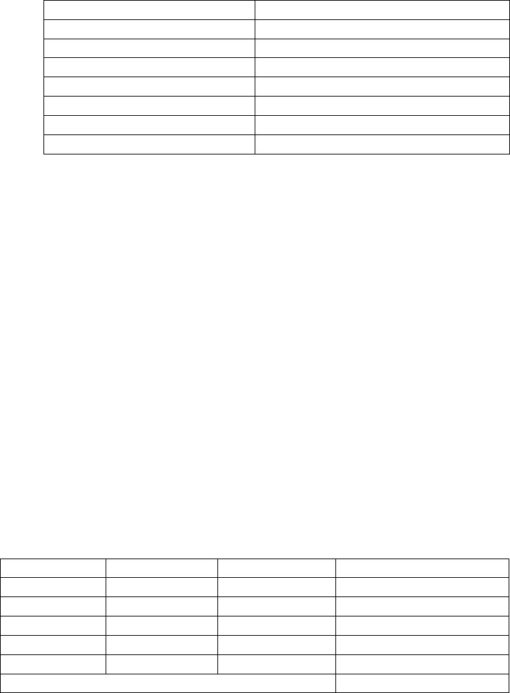
output in 1.82 seconds, fulfilling RV 10, as shown in table 1.
Table 1. Microcontroller Input-to-Output Latency Results
Test
Time(s)
1
2.17
2
1.50
3
1.61
4
2.04
5
1.74
6
1.89
7
1.59
8
2.05
Average
1.82
4.3.2 SD Card
The verification for the SD Card was included in the verification for the microcontroller. This is because
the requirement for the software, microcontroller, and SD card are co-dependent. In general, we did not
care what the individual latencies of each component were as long as the total time was maximum 2
seconds. Thus, if RV 10 is fulfilled, both the microcontroller and SD card are fulfilling their function.
4.3.3 Software
As previously mentioned, the software, microcontroller, and SD card in totality are required to take less
than 2 seconds of time. As such, we used the same verification procedure to verify the microcontroller,
SD card, and software. Additionally, we required a word error rate of no greater than 15%, as indicated
by RV 15. We ran trials of phrases with different word numbers to test the number of errors, calculated
the word error rate based on equation 4, and recorded the results in table 2.
(Eq. 4)
15
Table 2. Word Error Rate Test Results
Phrase (Word Number)
Word Error Rate (Percentage)
1
0
2
0
3
0
4
0
5
20
6
0
Average
3.33
4.4 Output System
4.4.1 LCD Screen
In order to verify the LCD screen, we wired it up to our microcontroller. We then adapted an open
source python script, updating it with correct pin assignments. This python script allowed us to output
arbitrary text to the LCD screen. We tested various inputs and verified that we got the same from the
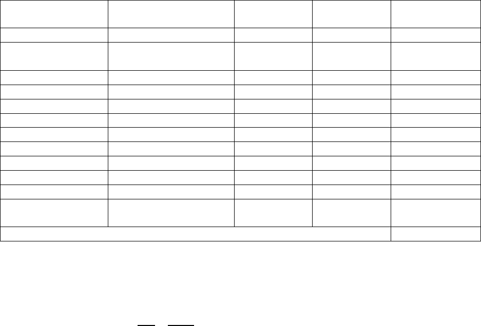
output, verifying RV 13. Additionally, we hooked up a multimeter to the input voltage and an ammeter
between the LCD screen’s logic and backlight ground pins and ground. This allowed us to calculate the
total power consumption of the LCD screen using equation 5. With approximately 105mW of power
consumed, we verified RV 14.
(Eq. 5)
Table 3. LCD Display Power Consumption Results
Voltage (V)
I
logic
(mA)
I
backlight
(mA)
Power Consumed (mW)
5.02
.15
20.8
104.75
5.04
.13
20.5
104.28
4.99
.15
20.85
104.79
5.06
.14
20.87
106.37
5.01
.15
20.69
104.41
Average Power Consumed
104.92
16
5. Costs
5.1 Parts
Table 4. Parts Costs
Part
Manufacturer
Retail Cost ($)
Bulk Purchase
Cost ($)
Actual Cost ($)
6 AA Battery Holder
Toolcool
$6.44
N/A
$6.44
2X 7805 5V 1.5A
Voltage Regulator
Adafruit
$0.75
$0.60
2 * $0.75
2X TO-220 Heatsink
Adafruit
$0.75
$0.60
2 * $0.75
Electret Microphone
Sparkfun
$5.95
$5.06
$5.95
20X Resistors
Digikey
$0.10
¢0.48
20 * $0.10
12X Capacitors
Sparkfun
$0.25
$0.23
12 * $0.25
5X UA741 Op amps
Texas Instruments
$0.58
$0.23
5 * $0.58
Raspberry Pi
Raspberry Pi Foundation
$35.00
N/A
$35.00
SD card
Transcend
$8.54
N/A
$8.54
LCD Display
Adafruit
$9.95
N/A
$9.95
T-Cobbler Plus
Adafruit
$7.95
$6.36
$7.95
AudioInjector
Soundcard
Flat Max Studios
$21.00
N/A
$21.00
Total
$105.73
5.2 Labor
Our fixed labor costs are estimated at $30/hr, 15hr/week, for 14 weeks, for 2 people, totaling to:
(Eq. 6)
Coming to a total cost of $31,605.73.
17
6. Conclusion
6.1 Accomplishments
We succeeded in verifying all modules of our design individually. In addition to this, almost all parts
were successfully integrated together. Our largest mishap was the unsuccessful integration of the LCD
screen with the rest of the circuit, which will be discussed in chapter 6.2. Our largest successes were
properly designing and constructing the bandpass filter circuit and utilizing software to successfully
convert speech to text.
6.2 Uncertainties/Challenges
We faced two major challenges in our final design. The first was the issue of soundcard to software
integration. The soundcard we used was a very recent product, and as such had very little
documentation for proper usage. Whenever we encountered a bug or issue with integration, we had
little guidance with debugging the problems. Without intimate knowledge of the software and
soundcard we used (which would be significantly outside the scope of this project), we ran into a lot of
problems with using pocket sphinx, eventually forcing us to switch to Bing Speech API to properly
convert microphone audio into text.
The other challenge was in our soundcard-microcontroller-LCD integration. Late in testing we discovered
that the soundcard and LCD screen use the same bus on the Raspberry Pi for communication. This
caused software deadlocks whenever attempts to run the full circuit were made, culminating in our
failure to display audio onto the LCD screen. The Pi was only capable of handling microphone input or
LCD output, one at a time, rather than both simultaneously. This problem could have been remedied by
using a multichannel LCD display to pass the information from the microcontroller to the screen without
disrupting the microphone input.
6.3 Ethical considerations
There are several potential safety hazards with this project. First and foremost is the implementation of
an electronic device that is designed to be handled or worn. Aligning ourselves with the IEEE Code of
Ethics #1[10], we acknowledge the possible safety concerns of our idea, and will do everything in our
ability to ensure the safety of the wearer in our design. We believe that the benefits of communication
advancement outweigh the dangers of such an idea. In addition, we plan to ensure that our design
adheres to IP54 guidelines, in order to keep the product in working condition under rainfall (IP54). This
is due to the fact that our project was designed to be worn on the body, and should ideally function
outside in standard weather conditions.
6.4 Future work
Future design considerations were to fix the challenges we faced in the original design. As previously
mentioned, a multichannel bussing system could alleviate the problem of microphone/LCD display
deadlocking the microcontroller. In addition to this, further testing and understanding of soundcard
integration with the Bing Speech API could have yielded speech-to-text conversion without the use of
Wi-Fi.
18
We also considered adding additional features to the design for future projects. A button next to the
screen that allows a re-display of the past recorded phrases could have been implemented by writing
programs saving the text files and resending them to the LCD screen when requested.
In a much grander scope, future work could be done in using this device for language translation.
Currently language translation software is in very early stages, but in the future, such software could be
downloaded and used to not only communicate with hearing impaired individuals, but also with people
speaking different languages. Pocketsphinx already has speech-to-text for a variety of different
languages, and LCD screens can display a wide variety of non-English characters, so the main issue to
tackle would be properly converting text in one language into another, a problem that many top
companies are tackling today.
19
References
[1] “Deafness and Hearing Loss.” World Health Organization, Web. 06 Feb 2017.
<http://www.who.int/mediacentre/factsheets/fs300/en/>
[2] "Communicating with People with Hearing Loss." UCSF Medical Center. Web. 06 Feb. 2017.
<https://www.ucsfhealth.org/education/communicating_with_people_with_hearing_loss/>
[3] "Communicating with People who are Deaf or Hard of Hearing: Ada Guide for Law Enforcement
Officers." U.S. Department of Justice. Web. 06 Feb. 2017.
<https://www.ada.gov/lawenfcomm.htm>
[4] LM7805 Voltage Regulator Datasheet <https://www.fairchildsemi.com/datasheets/LM/LM7805.pdf>
[5] Electret Microphone Datasheet <http://cdn.sparkfun.com/datasheets/Sensors/Sound/CEM-
C9745JAD462P2.54R.pdf>
[6] Electret Microphone built-in preamp datasheet <http://www.ti.com/lit/ds/symlink/opa344.pdf>
[7] Raspberry Pi 3 Specs
<https://www.raspberrypi.org/documentation/hardware/raspberrypi/power/README.md>
[8] LCD Display Physical Design
<https://www.adafruit.com/products/181>
[9] CMUSphinx word error test on Raspberry Pi 3
<https://www.element14.com/community/roadTestReviews/2166/l/roadtest-review-a-raspberry-
pi-3-model-b-review>
[10] “IEEE Code of Ethics.” IEEE. Web. 08 Feb. 2017.
<http://www.ieee.org/about/corporate/governance/p7-8.html>

20
Appendix A Requirement and Verification Table
Table 5 System Requirements and Verifications
Verified?
Requirement
Verification
Yes
1. Battery bank supplies 7.5 - 9
V+/- 5% to the voltage
regulators
2. Hook up batteries to multimeter
3. Measure voltage at various charges
4. Verify that voltage remains within
provided range
Yes
2. Battery bank lasts for 30
minutes of on time (drawing
0.3 - 0.5A in the on state)
1. Hook up batteries to the entire circuit
2. Start recording time
3. Run circuit until batteries stop
functioning
4. Verify that batteries last as long as
necessary
Yes
3. All regulators must output 5V
(+/-5%) when provided with
proper input voltage from the
battery (7.5 - 9V)
1. Hook up voltage regulator circuit to
multimeter
2. Input battery as voltage source at
various charges (to test upper and lower
limits of voltage)
3. Determine if output falls into given
range of 5V +/- 5%
Yes
4. Microphone must be able to
convert audio with frequencies
above 300Hz and below 3kHz
to electrical signals
1. Hook up microphone to multimeter
2. Use test sounds from a computer or
cellphone that are around given Hz
ranges
3. Plot output data
4. Observe if microphone effectively picks
up data within ranges given
Yes
5. Microphone must be able detect
audio with intensities at the 50-
60db range
1. Hook up microphone to soundcard
2. Monitor db range and speak into
microphone
3. Determine if output is intelligible for
speech recognition
Yes
6. Microphone must be able to
detect audio within a 20cm
range
1. Hook up microphone to soundcard
2. Speak from within 20cm of microphone
3. Determine if output is intelligible for
speech recognition
Yes
7. Bandpass filter must filter input
audio to cut off below the
300Hz range
1. Hook up bandpass filter to oscilloscope
2. Use various test signals above and
below 300Hz
3. Graph data

21
4. Observe data to verify the cutoff
frequency
Yes
8. Bandpass filter must filter input
audio to cut off above the 3kHz
range
1. Hook up bandpass filter to oscilloscope
2. Use various test signals above and
below 3kHz
3. Graph data
4. Observe data to verify the cutoff
frequency
Yes
9. Soundcard must be able to
receive analog microphone
signal, convert it to digital
signal, properly sample digital
signal into audio signal, and
interface audio signal to user
programs
1. Hook up soundcard and microphone
properly
2. Use arecord to record a sample sound
wav
3. Verify that the input is the same as the
output
Yes
10. Time required of the
microcontroller to process
speech and output signals must
not exceed 2s including SD
card latency
1. Run speech recognition script with
various inputs
2. Instrument code to output timestamps
when speech is processed and text is
output
3. Take the difference in each case and
average the sum of the differences
Yes
11. Files written to disk must not
require more space than what is
available on the sd card.
1. Add “old file” deletion thread to speech
recognition program that runs every 5
minutes
2. Run speech recognition program for 6
minutes various times
3. Ensure that the sd card never runs out of
space
Yes
12. The 16x2 LCD display must be
visible from at least 1m away
1. Stand at increasing distances away
2. Attempt to read different words
displayed on LCD screen
3. Determine if LCD screen is legible at
required distance
Yes
13. Must be able to correctly
display input text onto LCD
screen via MCU output
1. Hook up LCD to MCU
2. Configure LCD software properly
3. Send various input phrases
4. Determine that the output matches the
input
Yes
14. Total power consumption for
the LCD display will be 105
mW +/- 10% when on
1. Power up LCD display with different
words and phrases
2. Measure both current and voltage
3. Calculate power consumed
4. Make sure it falls within parameters

22
Yes
15. Produce a test word error rate
of 15%+/- 5%
1. Speak variety of phrases of 1-5 words
2. Determine error with equation:
WER=S+D+I/(S+D+C), where S is the
number of substitutions, D is the number
of deletions, I is the number of
insertions, C is the number of correct
words.
3. Determine if WER is within 15%.
Yes
16. Only detect sound at
frequencies between 300Hz-
3kHz
1. Produce a variety of sounds at varying
frequencies and intensity
2. Determine correct frequency reading
based on if sound is detected on time
