
User and maintenance instructions
V DC or / V AC, - Hz.
Electric operated Centro-Matic
pumps PS
Date of issue March 2018
Form number 404372
Version 2

Contents
Safety . . . . . . . . . . . . . . . . . . . . . . . . . . .
Explanation of symbols used . . . . . . . . .
User’s responsibility . . . . . . . . . . . . . . . .
Environmental protection . . . . . . . . . . .
Service . . . . . . . . . . . . . . . . . . . . . . . .
Safety instructions . . . . . . . . . . . . . . . . .
Appropriate use . . . . . . . . . . . . . . . . .
Misuse . . . . . . . . . . . . . . . . . . . . . . . .
Exclusion of liability . . . . . . . . . . . . . .
Regulation for prevention of
accidents . . . . . . . . . . . . . . . . . . . . . . . .
General safety instructions . . . . . . . .
Operation, maintenance and repair . . . .
Repair . . . . . . . . . . . . . . . . . . . . . . . . .
Operation/maintenance . . . . . . . . . . .
Disposal . . . . . . . . . . . . . . . . . . . . . . .
Installation . . . . . . . . . . . . . . . . . . . . . . .
Installation and maintenance of
hydraulic hoses . . . . . . . . . . . . . . . . . . .
Lubrication hose lines . . . . . . . . . . . . .
Description . . . . . . . . . . . . . . . . . . . . . . .
Pump PS . . . . . . . . . . . . . . . . . . . . .
Reservoir sizes . . . . . . . . . . . . . . . . . .
Electrical connection . . . . . . . . . . . . . .
Description of operation . . . . . . . . . . . . .
Pump operation . . . . . . . . . . . . . . . . .
Pressure control/hold time/
vent cycle. . . . . . . . . . . . . . . . . . . . . . . . .
Pump with internal pressure
switch only. . . . . . . . . . . . . . . . . . . . . . . .
Pump with internal and external
pressure switch . . . . . . . . . . . . . . . . . . . .
Pump with internal pressure
transducer only . . . . . . . . . . . . . . . . . . . .
Pump with internal and external
pressure transducer . . . . . . . . . . . . . . . .
Vent cycle . . . . . . . . . . . . . . . . . . . . . . . .
Fill reservoir with grease . . . . . . . . . . . .
Air expel procedures for
pumps with follower . . . . . . . . . . . . . . . .
Stirring paddle . . . . . . . . . . . . . . . . . . . .
Low-level control . . . . . . . . . . . . . . . . . .
Pump with follower plate . . . . . . . . . . . .
Grease reservoir full of grease . . . . . . . .
Grease reservoir empty . . . . . . . . . . . . .
Keypad and display . . . . . . . . . . . . . . . . .
Membrane keypad . . . . . . . . . . . . . . . . .
Test display of membrane keypad . . . . .
Operating mode . . . . . . . . . . . . . . . . . . .
Malfunctions . . . . . . . . . . . . . . . . . . . . . .
Acknowledge fault . . . . . . . . . . . . . . . . . .
To acknowledge malfunction . . . . . . .
Program pump . . . . . . . . . . . . . . . . . . . .
Programming mode: Pump
with pressure switch . . . . . . . . . . . . . . . .
Programming mode: Pump
with pressure transducer . . . . . . . . . . . .
Review of pump parameters . . . . . . . . .
Operating mode . . . . . . . . . . . . . . . . .
Specifications . . . . . . . . . . . . . . . . . . . . .
Connections for V DC
pump . . . . . . . . . . . . . . . . . . . . . . . .
Connections for - V AC
/ Hz pump . . . . . . . . . . . . . . . .
Jumper settings for
pump PCB . . . . . . . . . . . . . . . . . . . . . . . .
Centro-Matic scematic with
PS pump . . . . . . . . . . . . . . . . . . . . . .
List of lubricants . . . . . . . . . . . . . . . . . . .
Dimensions . . . . . . . . . . . . . . . . . . . . . . .
Refill and maintenance . . . . . . . . . . . . . .
Pump with follower plate . . . . . . . . . .
Pump without follower plate . . . . . . .
Pump cleaning . . . . . . . . . . . . . . . . . .
CE Certification . . . . . . . . . . . . . . . . . . . .
Warranty . . . . . . . . . . . . . . . . . . . . . . . . .

NOTE
Emphasizes useful hints and
recommendations as well as information
for efficient and trouble-free operation.
CAUTION
Indicates a dangerous situation that can lead
to light personal injury or property damage if
precautionary measures are ignored.
WARNING
Indicates a dangerous situation that could
lead to death or serious injury if
precautionary measures are ignored.
DANGER
Indicates a dangerous situation that will lead
to death or serious injury if precautionary
measures are ignored.
Explanation of signal
words for safety
Safety
Read and carefully observe installation
instructions before installing/operating/
troubleshooting assembly. Assembly must
be installed, maintained and repaired
exclusively by persons familiar
with instructions.
Install assembly only after safety
instructions and guide have been read and
are completely understood.
Adequate personal protection must be
used to prevent splashing of material on skin
or in eyes.
Always disconnect power source
(electricity, air or hydraulic) from pump
when not being used.
Equipment generates very high grease
pressure. Extreme caution should be used
when operating equipment as leaking
material from loose or ruptured components
can inject fluid through skin and into body. If
any fluid appears to penetrate skin, seek
attention from doctor immediately.
Do not treat injury as a simple cut.
Tell attending doctor exactly what type of
fluid was injected.
Any other use not in accordance with
instructions will result in loss of claim for
warranty or liability.
• Do not misuse, over-pressurize, modify
parts, use incompatible chemicals, fluids,
or use worn and/or damaged parts.
• Do not exceed stated maximum
working pressure of pump or of lowest
rated component in system.
• Always read and follow fluid
manufacturer’s recommendations
regarding fluid compatibility, and use of
protective clothing and equipment.
• Failure to comply may result in personal
injury and/or damage to equipment.

User’s responsibility
To ensure safe operation of unit, user is
responsible for the following:
1 Pump/system shall be operated only for
intended use and design shall not be
modified or transformed.
2 Pump/system shall be operated only if it is
in proper functioning condition and if
operated in accordance with maintenance
requirements.
3 Operating personnel must be familiar
with owners manual and safety
instructions mentioned within, and
observe instructions carefully.
Correct installation and connection of tubes
and hoses, if not specified by Lincoln
Industrial, is user’s responsibility.
Lincoln industrial technical services will
gladly assist you with any questions
pertaining to installation.
Environmental
protection
Waste (e.g. used oil, detergents, lubricants)
must be disposed of in accordance with
relevant environmental regulations.
Service
Personnel responsible for handling of pump/
system must be qualified. If required, Lincoln
Industrial offers you full service in form of
advice, on-site installation assistance,
training, etc. Please contact technical service
department for assistance.
In event of inquiries pertaining to
maintenance, repairs and spare parts, model
specific data to enable technical services to
clearly identify components of your pump/
system is required; therefore, always
indicate part, model and series number.
Safety instructions
Appropriate use
Electric Centro-Matic pump PS has been
designed for automatic lubrication of
commercial vehicles, industrial, construction
and agricultural machines and wind power
plants.
PS pump has been designed for
intermittent operation and is not suitable for
continuous operation. Pump is capable of
supplying lubricants up to NLGI grade.
(† pages 36 – 38 for list of recommended
greases).
Misuse
Any use of PS pump that is not
mentioned in user manual will be regarded
as misuse. If PS pump is used or
operated in a manner other than specified,
any claim for warranty or liability will be null
and void.
Exclusion of liability
Manufacturer of PS pump will not accept
any liability for damages caused by:
• lack of lubricant due to an irregular
refilling of pump
• use of contaminated lubricants
• use of greases not pumpable or only
conditionally pumpable by PS pump
• inadequate disposal of used or
contaminated lubricants as well as of
components that have been in touch
with lubricant
• unauthorized modification of system
components
• use of unapproved parts
• operation without adhering to minimum
pause time and respectively maximum
lubrication time
Regulation for
prevention of
accidents
To prevent accidents, observe all city, state
and federal safety regulations of the country
product will be used.
General safety instructions
• Pump PS is designed for safe
operation.
• Incorrect use may result in bearing
damage caused by poor or excessive
lubrication.
• PS pump with follower can be
mounted vertically, horizontally or upside
down.
•
Pump without follower should be mounted
vertically upright only.
• Unauthorized modifications or changes to
an installed system are not admissible.
Any modification of pump must be subject
to prior authorization by manufacturer.
• Install components of PS pump in
such way that operator can always see
low-level position of pump reservoir.
• Each time reservoir has been refilled,
make sure no air has been trapped under
follower and pump is pumping lubricant.
NOTE
When using parts other than spare parts that
have been tested, serious damage may occur.
For operation of device always use original
parts made by Lincoln Industrial.
CAUTION
If personal injury or material damage occurs
as a result of inappropriate operation,
(e.g. if safety instructions are ignored or
resulting from an incorrect installation of
PS pump), no claims or legal actions may
be taken against Lincoln Industrial.

Operation,
maintenance and
repair
Repair
Repair should only be performed by
authorized and instructed personnel
familiar with instructions.
Operation/maintenance
Pumps PS:
• Must be refilled at regular intervals with
clean lubricant recommended by
manufacturer without air entrapments
under follower plate.
• Operate automatically. Regular check
(approximately every days) should be
made to ensure lubricant is pumped to all
lubrication points.
Disposal
Dispose of used or contaminated lubricants,
as well as of parts in touch with lubricant,
according to legal regulations pertaining to
environmental protection. Make sure to
observe safety data sheets of
lubricants used.
• Defective printed circuit boards should be
appropriately packed and returned
to factory.
Installation
• Any safety equipment already installed on
vehicle:
– should not be modified or made
ineffective.
– should only be removed for purpose of
installing system and must be
replaced afterwards.
WARNING
Before carrying out any maintenance or
repair on the PS pump, make sure that
all lubrication lines of the carrier unit
are depressurized.
Failure to comply may result in death or
serious injury.
CAUTION
Electric voltage present. In case of pumps
where grease is filled from top, power supply
must be switched off before lubricant is
filled in.
Failure to comply may result in personal
injury or damage to equipment.
WARNING
Pump PS must be installed by qualified
personnel. Connection of V AC must be
done according to National Electrical code.
Before installing or working on pump,
disconnect and lock out incoming power.
Failure to comply may result in death or
serious injury.
CAUTION
Never put your hand into open reservoir
while pump is running. Injury may occur if
pump is being filled from reservoir top.
Failure to comply may result in personal
injury or damage to equipment.
WARNING
Failure to observe safety instructions,
(e. g. touching electrically charged parts
when pump is opened, or improper handling
of pump PS) may cause serious injury or
death. If values specified in technical data are
exceeded, device may overheat. It may
damage pump PS and impair
electric safety.
Failure to comply may result in death or
serious injury.
CAUTION
Do not use pump in potentially explosive
applications.
Failure to comply may result in personal
injury or damage to equipment.
NOTE
Adhere to:
• installation instructions of vehicle
manufacturer with regard to all drilling and
welding procedures.
• specified minimum distance between holes
and upper/lower rim of frame or between
two holes.
NOTE
Route supply lines professionally. Firmly bolt
together any components subject
to pressure.
NOTE
Do not exceed maximum filling mark when
filling reservoir by means of pumps with large
delivery volume. Risk of burst if reservoir is
over-filled.

Fig. 2
Pump without follower plate
Fig. 1
Pump with follower plate
Installation and
maintenance of
hydraulic hoses
Lubrication hose lines
• must never be subjected to torsion
• must be installed twist-free
• must not rub against metal components
or edges
• are to undergo regular visual checks and
must be exchanged in the case of wear
(at latest years after installation)
Pay attention to non-linear installations
to allow for larger bending radius as
possible. Avoid kinks. In constricted
installation conditions, use pipe elbow
unions to avoid danger of kinking behind
hose socket. Use high pressure hydraulic
hose for lubrication lines.
8
10
1
3
5
9
7
4
6
2
Components of PS pump with follower
1 Reservoir
2 Mounting plate
3 Pump elements
4 Pump housing
5 Pump outlet
6 Relief valve
7 Keypad
8 Low-level control
9 Refill grease fitting connection
10 Top lid
11
10
3
9
7
4
6
5
2
8
1
Single-line pump PS, no follower
(Note: low-level control († Fig. 13,
page 16 and Fig. 16, page 19)
1 Reservoir
2 Mounting plate
3 Pump elements
4 Pump housing
5 Pump outlet
6 Relief valve
7 Keypad
8 Stirring paddle
9 Refill grease fitting
10 Stationary paddle
11 Top Lid
NOTE
Operational safety of PS pump can only
be ensured in case of professional installation
and maintenance of hose lines.

Pump P653S
•
pumps greases up to NLGI (per approved
list) at temperatures from – to °F
(–40 to 70 °C)
• develop maximum pressure up to
psi (240 bar) with pressure switch
and up psi (317 bar) with
pressure transducer.
Reservoir sizes
• l transparent plastic reservoir
• l transparent plastic reservoir
• l transparent plastic reservoir
• l transparent plastic reservoir
Electrical connection
• For industrial / V AC applications
PS pumps are provided with -pole
square type connector. Electric cable is
provided by installer.
• For mobile applications PS pumps are
equipped with an electric cable
ft (10 m) and -pole bayonet
type connector.
Description
PS pump is designed for single line
parallel Centro-Matic type lubrication
systems. Pumps integrated design includes
all necessary components to support
Centro-Matic lubrication systems:
• controller to program and monitor
lubrication cycle
• choice of internal pressure switch or
internal pressure transducer
• internal vent valve
• three pumping elements connected
together
• external pressure relief valve
• reservoir low-level control
• end of lubrication line pressure switch or
pressure transducer choice
• contacts for remote monitoring
• V DC or / V AC power supply
option, etc.
Pump can supply adequate lubricant to
bearings using SL-V, SL-V XL, SL-, SL-
and SL- injectors. Number of injectors
should be based on output of the pump
being . in
/minute (24,5 cm
3/
minute).
Pump for / V AC power supply can
be installed in any stationary industrial type
of applications requiring lubrication for the
same number of medium size bearings.
Pump basic model can be supplied with
follower plate or without follower plate.
Follower plate is recommended in stationary
industrial type applications with heavy
consistency greases (NLGI and ) and for
pumps used at low temperatures
applications in all installations.
Typical Centro-Matic system schematic is
shown on page 35.
NOTE
Installations using SL- and SL- Lincoln
injectors can lubricate more than
bearings.
CAUTION
Use only supply line hose and fittings that are
appropriate for programmed/set system
pressure.

Identification code P653S pump
Code example PS - - X - L - F - - A - AS
Pump mode, basic
Reservoir size and configuration
= l, transparent plastic
= l, transparent plastic
= l, transparent plastic
= l, transparent plastic
X = grease pump
L = low level control
BO = without follower
F = with follower
Power supply
= V DC
AC = - V AC, - Hz.
Electrical cord and connections
A DC:
– ft. (10 m) cord, conductors
A DC:
– ft. (10 m) cord, conductors
– ft. (10 m) cord, conductors with
bayonet plugs for external pressure
switch or transducer
A AC
– ft. (10 m) cord, conductors
- -pole square plug
A = AC
– ft. (10 m) cord, conductors
- -pole square plug
– ft. (10 m) cord, conductors with
bayonet plugs for external pressure
switch or transducer
Pressure control, PCB setting.
AS – S - pressure switch
(† Jumper setting table)
AS – AS = pressure transducer (†
Jumper setting table)
Example: PS-XLF--A-AS:
Pump consists of the following:
V DC grease pump with follower
Four liter reservoir
Low-level control
Internal pressure switch
ft. (10 m) power cord
External pressure switch with ft.
(10 m) cord

Jumper setting (plugged = x, unplugged = o)
External pressure switch or external pressure transducer is included with pumps that have feature
of external pressure monitoring. Also included is a ft. (10m) cord to connect external monitoring
device to pump.
Jumper setting combinations – Centro-Matic pumps
Application:
Industrial (s) -o:
Time (TC) or count
control (CC):
Number of
pressure
switches or
transducers
Low level
control
F fault relay;
(31) switch to
F fault relay:
(31) switch to
Pump combinations Mobil (m) -x TC: - o; CC - x o = ; x = NO - o; NC - x ground - x ground - x
Pressure
switch
AS Industrial
(AC) (S)
o o o x x x
AS o o x x x x
AS o o o o x x
AS o o x o x x
AS Mobile
(DC) (M)
x o o x x x
AS x o x x x x
AS x o o o x x
AS x o x o x x
Pressure
transducer
AS Industrial
(AC) (S)
o o o x x
AS o o x x x
AS o o o o x
AS o o x o x
AS Mobile
(DC) (M)
x o o x x
AS x o x x x
AS x o o o x
AS x o x o x

Fig. 4
Idle run of switch joint on venting element
Fig. 3
Disassembled pump housing - view from bottom
Description of
operation
Pump operation
Drive
• Pump housing consists of the following
components: gear motor, final gear drive,
three pumping elements connected
together by internal passages and vent
valve. Pump can be configured with
internal pressure switch or transducer.
• Gear motor shaft is connected to final
stage gear drive. Final gear has
incorporated eccentric and cam to drive
pumping elements and to control internal
vent valve († Fig. 4).
• Vent valve is a two way normally closed
spring biased valve.
• Pressure switch is not adjustable and
preset to psi (240 bar).
• Pressure transducer is adjustable.
Factory setting is psi (240 bar).
Pressure setting of pressure transducer
can be adjusted from to psi
(96 to 317 bar) in
psi (6,9 bar) increments.
Lube cycle/pressurization
• Motor turns cam (7) clockwise to start
lubrication cycle. As soon as pump starts
to operate, display rotating segment is
turning clockwise also
(† Fig. 20, page 20). Maximum time to
build preset pressure is minutes. If
pump does not build preset pressure, fault
signal E or E will appear on display.
• Vent valve (1) is normally closed and stays
closed during lubrication cycle, preventing
lubricant flow back to reservoir († Fig. 4).
• Output of three pump elements (4)
(† Fig. 3) is combined by internal
passages.
• Eccentric drives pump elements to pump
lubricant from reservoir and build line
pressure.
• Cam (7) will keep vent valve (1) closed.
• Supply line can be connected to any one of
the pump element outlets. Remaining two
pump elements outlets should be plugged.
1 Venting element
2 Integrated pressure switch
3 Motor
4 Pump elements with integrated lubrication lines
1
3
2
4
1 Inactive venting element
6 Switch joint
7 Cam (driven clockwise by motor)
1.69 in
(43 mm)
2.05 in
(52 mm)
1
6
7

Fig. 9
Venting in vent valve
Fig. 8
Rotating segmented display during
venting (counter-clockwise)
Fig. 7
Display during change of moving direction
of pump motor
Fig. 6
Display during braking application of
pump motor
Fig. 5
Activated cycle diagram
1.69 in
(43 mm)
2.05 in
(52 mm)
1
6
7
1 Activated venting element
6 Activated vent lever
7 Cam (driven by motor counterclockwise)
1 Venting element
1.1 Inlet hole
1.2 Outlet hole
8 Plunger, venting
1
1.1
1.2
8

Fig. 12
Fig. 11
Fig. 10
Pump element Z7 for internal lubricant crossporting
Pump element operation
Pump element († Fig. 13 and
14, pages 16 and 17) is a single stroke
spring-based pump. Motor drives
eccentric (1). Eccentric is in constant
contact with plunger (2).
Compression spring (3) is pushing
plunger (2) to open lubricant passage to
create vacuum to prime pump with lubricant
from reservoir. Check valve (4) is closed to
isolate supply lines of system.
Eccentric (1) is pushing plunger (2) in
opposite direction to pump lubricant,
developing operating pressure.
Check valve (4) is open to pass lubricant to
supply lines.
Body of pump element has a
lateral outlet (5) († Fig. 12) for lubricant
crossporting to internal material passages to
combine outlet of all three pump elements.
Any one of the three elements can be
used as a pump outlet. Remaining two
elements should be closed with
plug (A) († Fig. 12).
A
5
3
2
A Closure plug (connection G
1
/4 in for main line)
2 Piston
3 Spring
5 Lateral outlet for lubricant crossporting
1
2
3
4
1
2
3
4
NOTE
Use only pump elements designed for
operation in PS pump. No other pump
elements should be used. See parts listing
for correct pump element part number.

Pressure control/hold
time/vent cycle
Pump with internal
pressure switch only
Internal pressure switch will close at
psi (240 bar) and open at
psi (179 bar).
After pump starts a lubrication cycle,
motor stops when pressure at pump reaches
preset pressure of psi (240 bar).
Pump will go through two holding periods,
H and H.
Holding time (H1)
• Internal pressure switch must stay closed
for consecutive seconds before going to
H. If internal pressure switch opens
during seconds, pump will restart and
run until internal pressure switch closes.
Holding time (H2) – will last
for 30 seconds
• At end of seconds, if internal pressure
switch is closed, pump will begin a vent
cycle.
• If at the end of seconds internal
pressure switch is open, pump will restart
and run until internal pressure switch
closes. When it closes a vent cycle will
take place.
• If at the end of seconds internal
pressure switch is closed, but during H
hold time internal pressure switch did
open, pump will restart and pump for
seconds before vent cycle begins.
Possible faults
• E Fault – a failure to build pressure at
pump within allotted minutes of
pumping time.
• E Fault – a failure to vent at pump.
Internal pressure switch has seconds to
open when motor reverses to
locate vent position.
Pump with internal
and external
pressure switch
Internal pressure switch will close at
psi (240 bar) and open at
psi (179 bar. External pressure switch
will close at psi (172 bar) and open at
psi (131 bar).
After pump starts lubrication cycle,
motor stops when pressure at pump reaches
preset pressure of psi (240 bar).
Pump can go through three holding periods,
H, H and H.
Holding time (H1)
Internal pressure switch must stay closed for
consecutive seconds before going to H.
If internal pressure switch opens during
seconds, pump will restart and run until
internal pressure switch closes.
Holding time (H2) – will last
for 30 seconds
• At the end of H, if internal pressure
switch is closed and external pressure
switch is closed, pump will begin
vent cycle.
• At the end of H, if internal pressure
switch is open or both internal and
external pressure switches are open, an
H will appear on the display. Pump will
turn on again and pump until internal
pressure switch is closed. When both
internal and external pressure switches
are closed vent cycle will take place.
• If at the end of H internal pressure switch
is closed but external pressure switch is
open, pump will turn on for seconds and
then stop and wait until external pressure
switch closes. H will appear on display.
When both internal and external pressure
switches are closed, vent cycle will take
place.
Holding time (H3)
• Holding time H will remain until both
internal and external pressure switches
are closed and then vent cycle will take
place. If both pressure switches do not
close within allotted pumping time of
minutes, alarm will occur. If internal
pressure switch opens during H, it will
repump until internal pressure switch
closes.
Possible faults
• E Fault – a failure to build pressure at
pump within allotted minutes of
pumping time.
• E Fault – a failure to build pressure at the
end of the supply line.
• E Fault – a failure to vent at pump.
Internal pressure switch has seconds to
open when motor reverses to locate vent
position.
• E Fault – a failure to vent at the end of
the supply line. External pressure switch
must be open before next lube cycle
takes place.

Pump with internal
pressure transducer
only
Internal pressure transducer is factory set to
close at psi (240 bar). Internal
transducer can be adjusted from
to psi (96 to 317 bar)
using key pad on pump. Adjustment is in
psi (, bar) increments. Internal
pressure transducer is set to open at
psi (62 bar) below point where it closed.
After pump starts lubrication cycle, motor
stops when pressure at pump reaches preset
pressure. Pump will go through two holding
periods, H and H. The following will use
factory setting of psi (240 bar) and
opening pressure of psi (179 bar).
Holding time (H1)
• Internal pressure transducer must reach
psi (240 bar) and stay above
psi (179 bar) for consecutive
seconds before going to H. If internal
pressure transducer drops below
psi (179 bar) during seconds,
pump will restart and run until internal
pressure transducer reaches
psi (240 bar).
Holding time (H2) – will last
for 30 seconds
• At the end of seconds, if internal
pressure transducer is above psi
(179 bar), pump will begin a vent cycle.
• If at the end of the seconds internal
pressure transducer is below
psi (179 bar), pump will restart and
run until internal pressure transducer
reaches psi (240 bar). When this
happens vent cycle will take place.
• If at the end of seconds the internal
pressure transducer is above
psi (179 bar), but during the H hold
time internal pressure transducer dropped
below psi (179 bar), pump will
restart and pump for seconds before
vent cycle begins.
Possible faults
• E Fault – a failure to build pressure at
pump within allotted minutes of
pumping time.
• E Fault – a failure to vent at pump.
Internal pressure switch has
seconds to open when motor reverses
to locate vent position.
• E Fault – a failure to vent at pump.
If at the end of the pause time pressure of
internal pressure transducer has not
dropped below psi (62 bar), an E
fault will occur.
Pump with internal
and external
pressure transducer
Internal pressure transducer is factory set to
close at psi (240 bar).
Internal transducer can be adjusted from
to psi (96 to 317 bar) using key
pad on controller. Adjustment is in
psi (6,9 bar) increments. Internal press-
ure transducer is set to open at
psi (62 bar) below point where it closed.
External pressure transducer is set to
close at psi (172 bar). Opening point of
external pressure transducer is adjustable
from to psi (14 to 69 bar).
It is factory set to open at psi (62 bar).
After pump starts a lubrication cycle,
motor will stop when pressure at pump
reaches preset pressure of
psi (240 bar). Pump can go through
three holding periods, H, H and H.
The following will use factory settings for
P and P.
Holding time (H1)
• Internal pressure transducer must reach
psi (240 bar) and stay above
psi (179 bar) for consecutive
seconds before going to H. If internal
pressure transducer drops below
psi (179 bar) during seconds,
pump will restart and run until internal
pressure transducer reaches
psi (240 bar).
Holding time (H2) – will last
for 30 seconds
• At the end of H, if internal pressure
transducer is above psi (179 bar)
and external pressure transducer has
reached psi (172 bar), pump will
begin vent cycle.
• At the end of H, if internal pressure
transducer is below psi (179 bar), or
both internal pressure transducer is below
psi (179 bar) and external pressure
transducer has not reached
psi (172 bar), an H will appear on
display. Pump will turn on again and pump
until internal pressure transducer has
reached psi (240 bar).
When internal pressure transducer is
above psi (179 bar) and external
pressure transducer has reached
psi (172 bar), vent cycle will
take place.
• If at the end of H internal pressure
transducer is above psi (179 bar)
but external pressure transducer has not
reached psi (172 bar), pump will
turn on for seconds and then stop and
wait until external pressure transducer
reaches psi (172 bar). H will appear
on display. When internal pressure trans-
ducer is above psi (179 bar) and
external pressure transducer has reached
psi (172 bar) vent cycle will
take place.
Holding time (H3)
• Holding time H will remain until
internal pressure transducer is above
psi (179 bar) and external pressure
transducer has reached
psi (172 bar), and then vent cycle
will take place. If both pressure transducers
do not reach preset settings within
allotted pumping time of minutes, an
alarm will occur. If internal pressure
transducer drops below psi
(179 bar) during H it will repump until
internal pressure transducer reaches
psi (240 bar).
Possible faults
• E Fault – a failure to build pressure at
pump within allotted minutes of
pumping time.

• E Fault – a failure to build pressure at the
end of the supply line.
• E Fault – a failure to vent at pump.
Internal pressure transducer has
seconds to drop below psi
(179 bar) (when motor reverses to locate
vent position).
• E Fault – a failure to vent at the end of
the supply line. External pressure
transducer has to drop below psi
(62 bar) before next lube cycle takes place.
Vent cycle
• After pump completes preset hold time
and pump maintains specified pressure,
controller will initiate a vent cycle. Vent
cycle will last for ten seconds.
• Motor will turn counterclockwise to
engage and open internal vent valve.
Display’s rotating segment is turning
counter clockwise.
• Motor will stop in a position to hold vent
valve open. Hr will be displayed for
remainder of seconds.
• Cam (7) († Fig. 6, page 11) engages vent
lever (6) depressing vent valve plunger (8)
(† Fig. 10, page 12). This opens valve
passage of the supply line to the reservoir.
• Lubricant is flowing back to reservoir
venting pressure from system. Valve stays
open during pause time.
Fill reservoir with grease
Use grease fitting (9) († Fig. 1, page 6) to fill
reservoir. Filling reservoir for first time is
critical to proper pump operation.
Make sure no air is trapped under follower
plate. Grease should be in full contact with
surface of follower. It’s recommended to run
motor by initiating lubrication cycle during
first reservoir fill. Stirring paddle of running
motor will help to evenly spread grease
under follower minimizing air pockets.
Air expel procedures for
pumps with follower
Disconnect plug (8) († Fig. 1, page 6) and
unscrew top lid (1) of reservoir. Remove lid
and spring from pump. Start filling pump. As
soon as grease level starts lifting follower,
stop filling and check for air trapped under
follower. Use plastic wire tie to expel air:
push plastic tie between follower seal and
wall of reservoir and push follower with hand
until it completely contacts grease. Replace
lid and connect low-level electric plug. Finish
filling of reservoir.
Stirring paddle
Stirring paddle (3) († Fig. 2, page 6) is
attached to motor and rotates during
lubrication cycle. Paddle is working grease in
reservoir to make it more pumpable and at
same time pushing grease down into
housing and pumping elements to
prevent cavitation.
Low-level control
Pump model PS is equipped with a low-
level grease control as a standard feature.
Pump with follower
plate
Low-level control electromagnetic reed
switch is located in central rod of reservoir.
Switch is sealed and does not have any
contact with grease. Follower plate bushing
has a magnet. As soon as follower reaches
preset position at bottom of reservoir,
magnetic field will close switch to indicate
low-level of grease. Control panel display LL
will be on. Pump can be operational for
some time since there is a small amount of
grease left under follower in reservoir and
pump housing. Pump should be refilled as
soon as possible. Always refill pump to
maximum of reservoir capacity. LL display
should be off as soon as pump is refilled.
CAUTION
Make sure there is no air trapped under
follower plate. Grease should be in full
contact with surface of follower. Use air
expelling procedures if necessary.
Failure to comply may result in personal
injury or damage to equipment
WARNING
Follower spring is completely compressed if
reservoir is full of grease. Exercise extreme
caution removing top of pump.
Failure to comply may result in death or
serious injury.

Fig. 13
Pump without follower plate
Grease reservoir full
of grease
• Stirring paddle rotates clockwise during
lubrication cycle († Fig. 13).
• Pivot bracket of stirring paddle (B) is
completely submerged into grease and
grease resistance to paddle rotation
guides bracket with round magnet
inward to orbit (A).
• Control cam (3) guides pivot bracket with
magnet and outwards, in direction of
reservoir wall. Since reservoir is full,
grease resistance guides pivot bracket
inward to orbit (A) as soon as bracket
passes cam (3).
Switching parts of low-level control for grease (when reservoir is filled).
1 Pivot bracket with round magnet
3 Control cam
A Inner orbit of round magnet
B Position of pivot bracket (LL not activated)
1
3
B
A
• Magnet and low-level switch (2)
(† Fig. 14, page 17) are not aligned and
switch can not be activated.
NOTE
Above mentioned switching parts (1 to 3)
(† Fig. 13 and 16, page 19) must not be
used with fluid grease or oil. In this case, use
float magnetic switch.

Fig. 14
Pump without follower plate
Grease reservoir
empty
• Control cam (3) guides pivot bracket with
magnet (1) outward. Since there is no
grease resistance, bracket with
magnet (1) will stay outward in orbit C.
• Magnet (1) will align with low-level switch
and activate LL indicator on pump display.
C
2
1
D
3
Switching parts of low-level control for grease (when reservoir is empty).
1 Pivot bracket with round magnet.
2 Low-level switch
3 Control cam
C Outer orbit of round magnet
D Position of pivot bracket (LL activated)

Fig. 15
P653S membrane keypad
1 Display
2 Key for acknowledgment of fault indications and changing programming screens
3 Key for triggering additional lubrication cycle and for changing programming values
1
2
3
Keypad and display
Membrane keypad

Fig. 19
Display of a low-level indication
Fig. 18
Green circulating illuminated segment,
lubricating time, pump is running.
Fig. 17
Green segment left and right are on/
Ignition switch closed (on).
Fig. 16
Green segment right, power supply On,
ignition switch open (OFF).
Test display of
membrane keypad
Operating mode
• If there is only one segment on in lower
right-hand corner, this indicates that
ignition switch is open. If ignition switch is
open and right segment is flashing, this
indicates a fault condition. Closing ignition
switch display will indicate what type of
fault has occurred.
• If ignition switch opens during lubricating
time, lube cycle will be completed.
• When switching on ignition switch,
left-hand segment in display
window lights up († Fig. 17).
• During lubricating time of pump,
circulating illuminated segment appears in
display window of membrane
key pad († Fig. 18).
• If power supply is interrupted during
pause time, pause time continues at point
of interruption after switching power
on again.
• If power supply is interrupted during
lubricating time operating time will start
at beginning after switching power
on again.
Segment
Test display is made when voltage is
applied: all segments and decimal points are
illuminated for seconds.
When power is applied to pump display will
indicate if pressure switch or pressure
transducer is connected to pump. Example
indicates an internal pressure switch.
There are four possibilities:
S Internal pressure switch
T Internal pressure transducer
TT Internal and external pressure
transducer (must be connected)
SS Internal and external pressure switch
(must be connected)
EP will briefly appear after display test.
If EP remains on after display test this
indicates that remote lube pushbutton is in
closed position or keypad push-button is
defective.
NOTE
If low-level signal occurs during lubricating
time, current operating cycle will still be
completed; however pump does not switch
on automatically any more. It can only be
switched on again by manual lube cycle.
Furthermore, it is not possible to change to
programming mode while there is a low-level
signal.

Fig. 24
Display of malfunction E4, failure to vent
at end of line.
Fig. 23
Display of malfunction E3, failure to vent
at pump.
Fig. 22
Display of malfunction E2, failure to build
pressure at end of line.
Fig. 21
Display of malfunction E1, failure to build
pressure at pump.
Fig. 20
Display of holding time.
Display is indicating holding times when
pump reaches preset pressure.
Malfunctions
• If there is no feedback from pressure
switch or pressure transducer within
minutes of pumping time, pump
switches off immediately. One of the fault
signals E1 to E4 († Error, Fig. 21 to
26, page 21) will be shown flashing in
display of membrane keypad.
E1 fault is a failure to build pressure at
pump.
• If either pressure switch or pressure
transducer fails to actuate within
minutes of pumping, this fault will
occur.
E3 fault is failure to vent at pump.
• Failure of internal pressure switch to open
during seconds that pump motor
reverses to locate the vent position.
• Failure of internal pressure transducer to
drop psi (62 bar) below P
parameter (P minus psi (62 bar))
during seconds that pump
motor reverses to locate vent position.
• If at the end of the pause time internal
pressure transducer has not dropped
below psi (62 bar), an E3 fault
will occur.
E2 fault is a failure to build pressure at the
end of the supply line. You must use an
external pressure switch or pressure
transducer to detect this.
• If either external pressure switch or
pressure transducer fails to reach
psi (172 bar) within minutes of
pumping, this fault will occur.
E4 fault is failure to vent at the end of the
supply line. Must use external pressure
switch or pressure transducer to detect this.
• If at the end of the pause time external
pressure switch has not opened, an E4
fault will occur.
• If at the end of the pause time external
pressure transducer has not dropped
below P8 parameter, E4 fault will occur.
NOTE
If malfunction is present, E1, E2, E3 or E4 will
be flashing. Pump does not switch on
automatically any longer. It can only be
triggered via an additional lubrication cycle.
Furthermore, a change to programming
mode is not possible while in alarm.

Fig. 26
Operator key to acknowledge fault.
Fig. 25
Operator key to trigger additional
lubrication cycle.
To trigger additional lubrication cycle
via pushbutton, press button for
seconds.
To trigger additional lubrication cycles
externally
• Press pushbutton to trigger additional
lubrication cycles externally.
Press pushbutton for seconds.
– Mobile pump w/ ignition switch open
- up to two times
– Industrial pump w/machine switch open
– unlimited
NOTE
Existing fault signals († Fig. 19 to
26, page 19) must be acknowledged before
triggering an additional lubrication cycle.

Factory settings for parameters
Programming steps Factory setting Description
P Pause time – to hours
Pause time – to minutes
NO Output of both fault relays
NO (normally open)
NC (normally closed)
Two options for signalling a fault
o1 (Option 1)
F relay contact
a) Low-level fault will cause F contact to repeatedly open and close.
b) Pressure fault will cause F contact to close and stay closed.
F relay contact
Low-level fault or pressure fault will cause F contact to close and stay closed.
o2 (Option 2)
F fault relay’s contact will close on a low-level fault
F fault relay’s contact will close on a pressure fault
Both contacts can be used for remote signalling.
SP Option to have pump start with pause time or lube cycle.
SP – Pump starts with a pause time
SO – Pump starts with a lube cycle
P7 programming step will only appear on pump with internal pressure transducer. (Reading x )
x = psi. psi (241 bar) is maximum pressure that pump will build. Adjustable
from to psi (96 to 317 bar) in psi (6,9 bar) increments.
P8 programming step will only appear on pump with external pressure transducer.
(Reading x ) x = psi. psi (62 bar) is where = external pressure transducer will
open (vent) adjustable from to psi (13 to 69 bar) in psi (6,9 bar) increments.

Acknowledge fault
Display Press
To acknowledge malfunction
• Flashing display changes into
continuous light by pressing button
(acknowledging). By acknowledging fault
signal, flashing E1, E2, E3, E4 or LL
changes into permanent light.
• Messages that have been acknowledged
but not yet remedied will flash again after
pump is switched off and on again.
• After fault has been acknowledged, no
more lube cycles will take place until
successful manual lube cycle has
taken place.
< sec.
< sec.
< sec.
< sec.
< sec.

Step 2
Step 1
Program pump
Programming mode:
Pump with pressure
switch
Press
> sec.
P1: Setting of hours
When releasing two buttons, currently set
value appears. Example: factory-set value:
hour. Hour is indicated by dot on right-
hand side.
Press button.
Settings are made in one direction:
, , , ,.... hours
Button pressed once: increase by hour
Button pressed continuously: quick
sequence
Example: hours
Display
Setting of pause time P1 (hours)
and P2 (minutes)
To access programming mode, press both
buttons at the same time > seconds, so
that P1 appears in display.
Programming options: Pause time:
P1 – hours
P2 –
minutes
Min. pause time minutes
Max. pause time hours
minutes
Display
Press
Key Function
Key for modifying
parameters in pro-
gramming step
Key Function
Key for switching to
next programming
step
NOTE
Pump power must be on to start
programming.

Step 4Step 3
Display
Press
P2: Setting minutes
Press button, so that P2 appears in
display.
When releasing button, currently set
value appears (here factory-set value:
minutes).
Minute is indicated by dot on the left-
hand side.
Press button.
Settings are made in one direction: , , ,
, , , .... min
Button pressed once: increase by
minute
Button pressed continuously: quick
sequence. Example: minutes
P4: Programming of output signal for both
alarm relays. Default setting on printed
circuit board for alarm contacts is switching
to battery minus.
Press button so that P4 appears in display.
When releasing button, currently set
value appears in display (here factory-set
value NO, normally open contact). On fault
condition alarm contact will close.
Press button.
External fault contact is modified by
programming it as NC normally closed
contact. On a fault condition alarm
contact will open.
Display
Press
Display
Press
Display
Press
NOTE
If hours are set to 00, display will show
minimum pause time of minutes.

Step 6
Step 5
P5: Two options for signalling a fault
condition with alarm relays F1 and F2.
Press button so that P5 appears in display.
o (Option ) P4 is set to default of
normally open.
F1 relay contact
a) Low-level fault will cause F1
contact to repeatedly open and close.
b) Pressure fault will cause F1
contact to close and stay closed.
F2 relay contact
Low-level fault or pressure fault will cause
F contact to close and stay closed.
o (Option ) P4 is set to default of
Normally Open.
F1 fault relay’s contact will close on
low-level fault and stay closed.
F2 fault relay’s contact will close on
pressure fault and stay closed.
Both contacts can be used for remote
signalling.
Press pushbutton to change to option .
Factory Setting
Display
Press
Display
Display
Press
P6: Upon applying power to pump, program
whether it starts with pause time SP or
starts with lube cycle SO.
Press button, so that P6 appears
in display.
Currently set values appear as to whether
cycle is to start with pause time or
lubricating time.
Default setting for pump is set to start
with pause time SP (start pause time).
Press button.
Each time pump is switched on, it will
start with lubricating time SO (start
operation). After first lubricating time preset
pause time will be valid.
Display
Press
Display
Press

Step 7
Step 7
Complete programming
Press button. P - is displayed.
• Press key (additional lubrication) to
complete programming and to save
entered parameters.
Programming of pump with pressure switch
is complete.
Display
Press
Programming mode:
Pump with pressure
transducer
Complete steps 1 through 6
of pump with pressure
switch
P7: Programs setting of where
internal pressure transducer will close.
This is the maximum pressure that pump
can reach. Factory setting is
psi ( bar).
Press button to change value.
Reading x = Transducer setting in psi
x = psi (240 bar).
This setting is adjustable from
to psi (96 to 317 bar) in
psi (6,9 bar) increments.
Display
Press
Display
Press
NOTE
Always carry out programming completely in
order to save new values.
NOTE
If button additional lubrication is not
pressed within seconds, changed
parameters will not be saved and previous
programming remains valid.
NOTE
After completion of programming, check
parameter settings in operating mode once
again.
NOTE
P7 programming will only appear if pump
has internal pressure transducer.

Step 9
Step 8
P8: Programs setting of where external
pressure transducer will open. Opening point
(vent pressure) is adjustable from to
psi (13,8 to 69 bar) in psi (6,9 bar)
increments. Factory set opening point (vent
pressure) is psi (62 bar). Closing point of
external pressure transducer is fixed in
software at psi (172 bar).
Press button to change value.
Reading x = Transducer setting in psi
x = psi (62 bar).
Display
Press
Display
Press
Complete programming
Press button. P - is displayed.
• Press additional lubrication to complete
programming and to save entered
parameters.
Programming of pump with pressure
transducer is complete.
Display
Press
NOTE
P programming parameter only appears if
pump has external pressure transducer
connected.
NOTE
Always carry out programming completely in
order to save new values.
NOTE
If button additional lubrication is not
pressed within seconds, changed
parameters will not be saved and previous
programming remains valid.
NOTE
After completion of programming, check
parameter settings in review mode.

Display
Display
Display
after one sec.
. - (hours)
after one sec.
. - (minutes)
Review of pump
parameters
Press the button > seconds.
after one sec.
after one sec.
after one sec.
. - (minutes)
or
Display
Press
Display
Pause Time
Display
Display
Display
rP - (remaining
pause time)
Display
. - (hours)
Display
Will only appear if
pump has an
internal pressure
transducer.
Maximum pressure
pump will build.
Operating mode
after one sec.
after one sec.
after one sec.
after one sec.
after one sec.
Indicates that
internal pressure
transducer will
close at
psi (240 bar).
NO - Both relay
contacts are
normally open
o - Option - How
F and F will signal
a fault.
SP - Pump starts
with a pause time
Display
NOTE
The following display sequence is shown
once. The change of display occurs every two
seconds. Example of pump set to lubricate
each hours minutes and remaining
pause time (rP) is hours minutes.

after one sec.
Will only appear if
pump has internal
and external pressure
transducer. Setting
where external
transducer will open.
after one sec.
External pressure
transducer will open
at psi (62 bar).
Termination of
reviewing of
parameters.
Indicates software
version.
Next two displays
will indicate
software version.
or
Display
Display
Display
Display

Specifications
Electrical data for DC pump Pump elements K
Incoming voltage V DC -%/+% Piston diameter mm
Maximum current A Number of pumping elements (connected together)
External fuse A (time delay)
Reverse polarity protection Yes Tightening torques
Current draw with ignition switch open* mA Install pump . ft.lbf (18 Nm)
Electric motor on housing . ft.lbf (12 Nm)
Electrical data for AC pump Pump element in housing . ft.lbf (20 Nm)
Incoming voltage to V AC Closure plug in housing . ft.lbf (12 Nm)
Maximum current . A Return line connector on housing . ft.lbf (12 Nm)
Frequency to hz Tie rods for and l reservoir . ft.lbf (10 Nm)
Output from power supply V DC at A
External Fuse A (time delay) Weights
l reservoir with pump elements K,
without pressure relief valve, empty
Common electrical data for DC and AC pumps Pump PS without connecting cable . lb (9,6 kg)
Minimum pause time min. Pump PS version A . lb (10,6 kg)
Maximum pause time hours min. Pump PS version A . lb (11,2 kg)
Pause time increments min. or hour
Maximum pumping time min. 8 l reservoir, standard
Enclosure rating IP KK (NEMA X) Pump PS without connecting cable . lb (9,0 kg)
Pump PS version A . lb (9,6 kg)
Rating for fault relay contact: Pump PS version A . lb (11,2 kg)
Switching voltage Max. V AC/ V AC/
V DC
Switching current Max. A inductive 4 l reservoir, standard
Minimum switching current . mA Pump PS without connecting cable . lb (9,0 kg)
Pump PS version A . lb (9,7 kg)
Pump PS Pump PS version A . lb (10,5 kg)
Operating pressure with:
-pressure switch psi (240 bar) Weights above include the following equipment:
-pressure transducer psi (240 bar)
(transducer can be
adjusted from
to psi
(96 to 317 bar)
Pump kit with three pump elements, pressure relief valve,
grease filling (1,5 kg)
End of line pressure switch setting psi (172 bar)
(not adjustable)
Packing (cardboard box)
End of line pressure transducer setting psi (172 bar)
not adjustable
Attaching parts
Operating Instructions
End of the line transducer vent pressure is factory preset at
psi (62 bar). Pressure can be adjusted from
to 1 000 psi (14 to 70 bar) in psi (7 bar) increments.
Installation
Use only high pressure psi (344 bar) minimum hydraulic hose for
supply lines. Use only hose connection fittings that are appropriate for
programmed/preset system pressure.
Maximum distance using shielded wire for
pressure transducer*
ft (30 m)
Operating temperature range for DC pumps – to °F
)
(–40 to 70 °C)
)
Operating temperature range for AC pumps to °F
)
(0 to 50 °C)
)
Number of outlets (see instructions)
Lubricant up to NLGI grade
)
Output . in
/min
)
(24,6 cm
3
/min)
Reservoir sizes, L , , and
Lubricant line connection size G
1
/4 in
)
See list of approved and recommended lubricants. Contact Lincoln if lubricant is not in list.
)
Lubricant output is measured at + °F (21 °C) and backpressure psi (100 bar). Different pressures, temperature and grease can change output results.
* Indicates change.

PCB
Display
Ignition
switch
Neutral (if used)
switch
Red
1
2
30
15
Black
Keypad
3
3
Pump on
light
Yellow
5
4
On
Manual
Lube
7 5
Green
Low level
fault light
White
4
6
Z
F1
Remote
signaling
1)
Pressure
fault light
1)
Blue
Black
Remote
signaling
F2
6
7
2
1
31
10 A
fuse
30 31
24 V DC battery
31 Jumper
31 Jumper
M+ M–
8 9 10 11
M
6
Low level
switch
5 V
12
13
14
15
16
17
+
E
1
–
+
E
2
–
0.5 to 4.5 V
Pressure
transducer
Signal
Internal
Pressure
switch
5 V
0.5 to 4.5 V
Signal
External
Pressure
transducer
1
2
3
Pressure
switch
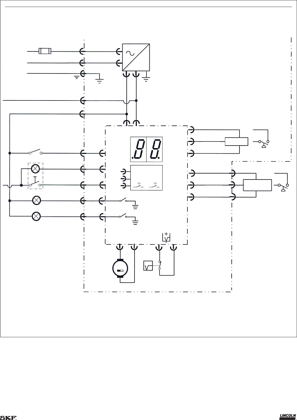
)
P programming parameter set to N.O.
P programming parameter set to Option .
)
Must connect red and black wires together if no machine switch is used. Can also use a special conductor bayonet plug (P/N --).
Diagram 1
Connections for 24 V DC 653 pump
X1
1
2
Black
Blue
Green/yellow
Black
White
Green
L1
3 A fuse
Neutral
grounding
wire
24 V DC
24 V DC
X2
2
1
Machine
switch
2)
Brown
Red
Black
Pump on
light
Yellow
3
3
Manual
lube
5
4
Green
7
5
15
On
Z
F1
F2
4
6
Low level
fault light
Remote signaling
Pressure
fault light
1)
6
7
X1 Square connector
X2 Round bayonet
2 1
30 31
Keypad
31 Jumper
31 Jumper
M+ M–
M
8 9
10
11
6
Low level
switch
12
13
14
15
16
17
+
E
1
–
+
E
2
–
5 V
0.5 to 4.5 V
Signal
5 V
0.5 to 4.5 V
Signal
Pressure
transducer
Pressure
switch
1
2
3
Internal
External
Pressure
transducer
Pressure
switch
Blue
White
Remote signaling
)
P programming parameter set to N.O.
P programming parameter set to Option .
Diagram 2
Connections for 110 – 230 V AC 50/60 Hz 653 pump

Keypad
Factory use only
F1 Fault relay for low level
F2 Fault relay for pressure
30 Relay contact switched to 24 V DC
31 Relay contact switches to ground
Default setting: Both relays switch
to ground (31) as shown.
S – Industrial (AC)
M – Mobile (DC)
W/ jumper – Mobile
W/O jumper – Industrial (AC)
Shown w/ jumper - Mobile
TC – Time control
CC – N/A
W/O jumper - Time control
1 – Internal PS or PT
2 – Internal and external PS or PT
W/O jumper – Only internal PS or PT
W/ jumper – Both internal and external
Shown w/o jumper-Internal
PS or PT only
NO – Normally open low level switch
Used with reservoir w/o a follower
NC – Normally closed low level switch
Used with reservoir w/ follower
W/O jumper – Normally open low level sw
W/ jumper – Normally closed low level sw
Shown w/ jumper – Pump has follower in
reservoir
Diagram 3
Jumper settings for 653 pump PCB

A
LL
M
2
3
6
5
P653S pump
4
P. S .
or
P.T.
To atmosphere
7
8
To bearings
To bearings
9
10
End of line
P.S. or P.T.
optional
1 Pumping housing ( pump elements)
2 Motor
3 Controller, key board with display
4 Internal pressure switch (P.S.) or
pressure transducer (P.T.)
5 Internal vent valve
6 Reservoir with low-level control
7 Pressure relief, psi (350 bar)
external
8 High pressure supply line
9 Injectors, SL-V, SL-, or SL-, SL-,
and SL-V XL injectors
10 Pressure switch (P.S.) or pressure
transducer (P.T.), external, optional.
A Power supply ( V DC or V AC,
optional)
NOTE
For proper operation of Centro-Matic
systems, vent pressure before next
lubrication cycle at end of line should be:
• Below psi (62 bar) for SL-V and SL-V
XL type of injectors.
• Below psi (41 bar) for SL- type of
injectors.
•
Below psi (13,8 bar) for SL-/ type
of injectors.
Diagram 4
Centro-Matic system schematic with P653S pump

List of lubricants
Centro-Matic pump can dispense
commercial greases up to NLGI at specified
operating temperature range.
Proven lubricants (see following
tables) have been tested by Lincoln with
regard to pumpability and venting
behavior. Lincoln recommends lubricants for
an application up to indicated minimum
delivery temperature in Centro-Matic
lubrication systems. During tests, lubricants
did not cause any damage due to
incompatibility with material used by
Lincoln.
Lubricants Lincoln recommends on basis of
manufacturer’s data sheet (see following
tables) can be used in Lincoln’s lubrication
systems up to indicated minimum delivery
temperature.
Grease pumpability and venting behavior
depend on ambient temperature range of
application, and may be different for same
NLGI grade of grease. This refers in particu-
lar to greases with more than % graphite.
Lincoln can test grease and develop
recommendations for specific applications.
NOTE
Absolute cleanliness is essential when
handling lubricants. Impurities will remain
suspended in lubricant and cannot settle.
This will result in damage to lubrication
system and thus to bearing.
NOTE
Consult Lincoln or Lincoln
distributor representative before using
lubricants with solid additives.
NOTE
Manufacturer of centralized lubrication
system can accept no liability for:
• damages due to use of greases that are
not, or only conditionally pumpable in
centralized lubrication systems
• damages on parts of centralized
lubrication system caused by chemical or
biological changes of lubricant used
• damages due to incompatibility with other
materials
Liability is limited to pumpable lubricants in
centralized lubrication systems.
Proven lubricants
Manufacturer Designation Thickener Minimum operating temerature
Caterpillar Moly Ultra NLGI Ca-complex °F (–12 °C)
Caterpillar Arctic Platinum NLGI Ca-complex Synthetic Base Oil – °F (–40 °C)
Caterpillar Auto–Lube NLGI Ca-complex °F (–12 °C)
Fuchs–Lubritech Stabil Eco EP Li/Ca – °F (–25 °C)
Fuchs Gleitmo Li – °F (–40 °C)
Fuchs Renocal FN Ca--OH-stearat – °F (–25 °C)
Fuchs Renoral FN Ca – °F (–20 °C)
Fuchs Renolit LZR t l Li – °F (–20 °C)
Fuchs Renolit HLT Li – °F (–25 °C)
Mobil Mobilith SHC Li-complex – °F (–25 °C)
Shell Retinax EPL Li--OH-stearat °F (–10 °C)
Shell Retinax CSZ Li/Ca – °F (–35 °C)

NOTE
Consult Lincoln or Lincoln distributor/
representative before using lubricants with
solid additives.
Proven lubricants (continued)
Lubricant recommendations based on manufacturer’s data sheet
Manufacturer Designation Thickener Minimum operating temerature
Agip F grease Ca °F (–15 °C )
Aral Multipurpose grease Li--OH-stearat °F (–15 °C )
Aral Multipurpose grease ZS / Li/Ca – °F (–20 °C)
Ava Avialith EP Li--OH-stearat °F (–15 °C )
BP Energrease LC Li-complex to °F (–15 to –10 °C)
BP Energrease MP–MG Ca-complex
Castrol/Tribol Molub Alloy Li--OH-stearat °F (–5 °C )
Castrol CLS – grease Li/Ca – to – °F (–30 to –25 °C)
Castrol Oliete Longtime Li – °F (–20 °C)
Castrol Optimol Olit EP Li – °F (–20 °C)
DEA Glissandro Li--OH-stearat to °F (–15 to –10 °C)
Esso Ronex Extra Duty Li-complex °F (5 °C)
Esso Ronex MP Li-complex °F (–5 °C )
Esso Beacon EP Li °F (–5 °C )
Esso Cazar K Ca °F (–15 °C )
Fiat Lubrificanti Comar Li – °F (–25 °C)
Kluber Centoplex DL Li/Ca – °F (–20 °C)
Kluber Isoflex NBU Ba – °F (–25 °C)
Kluber Kluberplex BEM – Ca-complex – °F (–20 °C)
Kluber Kluberplex BEM – Li-complex – °F (–25 °C)
Kluber Petamo GHY N Polycaramide °F (–15 °C )
Mobil Mobilgrease XHP Li-complex °F (–15 °C )
Mobil Mobilgrease XHP Li-complex °F (–10 °C)
Mobil Mobilgrease XHP Li-complex °F (–10 °C)
Mobil Mobilith SHC Li-complex °F (–5 °C )
Shell Alvania EP (LF) Li--OH-stearat to °F (–15 to –10 °C)
Shell Alvania EP (LF) Li--OH-stearat – °F ± °F (–10 °C ± 5 °C)
Shell Alvania RL Li--OH-stearat ± °F (–15 ± 5 °C )
Shell Malleus GL Gel GL °F (–10 °C), GL
°F (–10 °C), GL °F (0 °C), GL °F (5 °C )
Shell Retinax CS Li – °F (–20 °C)
Shell Retinax LX Li °F ± °F (–5 °C ± 5 °C )
Shell Retinax HDX Li/Ca – °F ± °F (–10 °C ± 5 °C)
Texaco Premium RB Li – °C (–4 °F)
Total Ceran AD Ca-complex °F (–15 °C )
Total Ceran LT Ca-complex – °F (–20 °C)
Total Ceran WR Ca-complex °F (–10 °C)
Zeller and Gmelin Divinol Lithogrease G Li-complex °F (–15 °C )

Proven lubricants (continued)
Biodegradable lubricants
Proven lubricants
Manufacturer Designation Thickener Minimum operating temerature
Aral Aralub BEB EP Li/Ca – °F (–25 °C)
BP Biogrease EP Li/Ca – °F (–25 °C)
Fuch-Lubritech Stabyl ECO EP Li/Ca – °F (–25 °C)
Lubricant recommendations based on manufacturer’s data sheet
Manufacturer Designation Thickener Minimum operating temperature
Autol Top Bio Ca – °F (–25 °C)
Avia Biogrease Li up to °F (0 °C)
DEA Dolon E Li °F (–15 °C )
Fuchs Pantogel S Li/Ca °F (–15 °C )
Kluber Kluverbio M- Polycarbamide – °F (–20 °C)
Lubricants for food and beverage industry
Lubricant recommendations based on manufacturer’s data sheet
Manufacturer Designation Thickener Minimum operating temperature
Aral Eural Grease EPF Al-complex °F (–5 °C )
Bremer and Leguil Rivolta F. L.G. - Al-complex – °F (–20 °C)
Elkalub GLS organic thickener °F (–10 °C)
Elkalub GLS /N inorganic thickener °F (–5 °C )
Elkalub GLS /N Al-complex °F (–10 °C)
Elkalub GLS /N Al-complex °F (–5 °C )
Fuchs Renolit G-G Bentonite °F (–5 °C )
Fuch-Lubritech Gleitmo M (KTW – drinking
water release
Li °F (–10 °C)
Interflon Fin food grease EP Al-complex °F (–5 °C )
Kluber Paraliq GA Al-complex °F (–10 °C)
Kluber Klubersuntha UH - Al-complex – °F (–20 °C)
Mobil Mobilgrease FM Al-complex °F (–15 °C)
Nordischer Maschinenbau Baader Special grease GLS /N Al-complex °F (–10 °C)
OKS Li--OH-stearat °F (–15 °C)
Optimol Obeen UF Al-complex °F (–15 °C)
Optimol Obeen UF Al-complex °F (–10 °C)
Rhenus Norplex AFD Al-complex °F (–5 °C )
Rhenus Norplex AFP Al-complex °F (–5 °C )
Rhenus Norplex AFS Al-complex – °F (–25 °C)
Rhenus Norplex AFW Al-complex °F (–5 °C )
Shell Cassida Grease ELS Al-complex °F (–15 °C)
Shell Cassida Grease ELS Al-complex °F (–10 °C)
Total Lubriplate FGL Al-complex °F (–5 °C )
Tribol Molub-Alloy FoodProof -FM Al-complex °F (–15 °C)
Tribol Molub-Alloy high-temperature grease PTFE °F (0 °C)
NOTE
Consult Lincoln or Lincoln distributor/
representative before using lubricants with
solid additives.

Fig. 27
Dimensions - P653S: 4 l reservoir
A1
A2
9.25 in
(235 mm)
9.45 in
(240 mm)
0.433 in
(11 mm)
5.85 in
(174 mm)
7.1 in
(180 mm)
Reservoir with follower plates: AC / A = . in (490,5 mm)
Reservoir with follower plates: DC / A = . in (470,5 mm)
Reservoir with stirring paddle: AC / A = . in (436 mm)
Reservoir with stirring paddle: DC / A = . in (416 mm)

Fig. 28
Dimensions, P653S, 8 l reservoir
B1
B2
0.433 in
(11 mm)
6 in
(154,5 mm)
7 in
(180 mm)
9 in
(235 mm)
9.5 in
(240 mm)
Reservoir with follower plates: AC / B = . in (577 mm)
Reservoir with follower plates: DC / B = . in (557 mm)
Reservoir with stirring paddle: AC / B = . in (536 mm)
Reservoir with stirring paddle: DC / B = . in (516 mm)

Fig. 29
Dimensions, P653S, 15 l reservoir
6.3 in
(160 mm)
0.41 in
(10,4 mm)
21.67 in
(550,5 mm)
C1
C2
9.25 in
(235 mm)
9.5 in
(240 mm)
0.43 in
(11 mm)
6 in
(154,5 mm)
7 in
(180 mm)
Reservoir with follower plates: AC / C = . in (834 mm)
Reservoir with follower plates: DC / C = in (814 mm)
Reservoir with stirring paddle: AC / C = . in (778 mm)
Reservoir with stirring paddle: DC / C = . in (758 mm)

Fig. 30
Dimensions, P653S, 20 l reservoir
6.3 in
(160 mm)
0.4 in
(10,4 mm)
D1
D2
0.43 in
(11 mm)
27 in
(685,5 mm)
6 in
(154,5 mm)
7 in
(180 mm)
9 in
(235 mm)
9.5 in
(240 mm)
Reservoir with follower plates: AC / D = . in (969,5 mm)
Reservoir with follower plates: DC / D = . in (949,5 mm)
Reservoir with stirring paddle: AC / D = . in (914 mm)
Reservoir with stirring paddle: DC / D = . in (894 mm)

Refill and
maintenance
Pump with follower plate
Use grease fitting (9) († Fig. 1, page 6) to fill
or refill reservoir. Make sure no air is trapped
under follower plate. Grease should be in full
contact with surface of follower. It is
recommended to run motor by initiating
lube cycle during first fill of reservoir. Stirring
paddle of running motor will help to evenly
distribute grease under follower minimizing
air pockets. Reservoir has a vent hole (11).
Fill grease to maximum follower position
until follower seal will slightly cross vent
hole. If air is still trapped under follower, add
some more grease to expel air through vent
hole.
Pump without follower plate
Use same grease fitting (9) to fill or refill
reservoir. It is recommended to run motor by
initiating lube cycle during first fill of
reservoir. Stirring paddle of running motor
will help to evenly distribute grease in
reservoir minimizing air pockets.
To speed up filling or refilling of pump,
grease fitting can be replaced with
1
/8 in (3,175 mm) (swivel connection to
attach hose from larger output filling pump).
Pump cleaning
Use petroleum or benzene based cleaning
solutions. Do not use tri-, perchloroethylene
or similar solvents. Do not use polar organics
such as alcohol, methyl alcohol, acetone or
similar solvents.
CAUTION
First time filling of reservoir with grease is
very critical for proper pump operation.
Pump may be shipped with small amount of
Fuchs Renocal FN /Lincoln grease used
for final testing and inspection.
Grease thickener is Ca--OH-stearat.
Check compatibility of Renocal FN /
Lincoln with grease and remove test grease if
necessary.
Failure to comply may result in personal
injury or damage to equipment.
CAUTION
Do not exceed maximum fill mark when filling
reservoir with large output fill or refill pump.
Risk of reservoir bursting if overfilled.
Failure to comply may result in personal
injury or damage to equipment.

Fig. 31
Pump mounting template
Pump mounting
plate
Top
edge
of
pump
8.19 in
(208 mm)
7.08 in
(179,83 mm)
1.437 in
(36,5 mm)

Troubleshooting
Mode of failure Solution
Pump motor does not run. No green right corner segment lit on
display († Fig. 16, page 19).
Check power supply and fuses.
Pump does not deliver lubricant but runs if manual lube
switch (3) is pushed († Fig. 15, page 18). No green left corner
segment lit on display († Fig. 17, page 19).
Connect ignition or machine switch per electrical schematic on
pages 28 and 29.
LL display is flashing. Reservoir is almost empty. Pump with follower - refill reservoir. Pump without follower – refill
reservoir and push switch (3) († Fig. 15) to initiate manual lube cycle.
E1 display is flashing. Pump failed to develop internal
pressure in minutes.
Push switch (2) († Fig. 15) to acknowledge fault. Initiate manual
lube cycle. Investigate and correct possible causes – air pockets, broken
line, connections leakage, worn pumping element, failed internal
pressure switch or pressure transducer. Initiate manual lube cycle.
E2 display is flashing. Pump failed to develop pressure at
the end of the line (pump with external pressure switch
or pressure transducer).
Push switch (2) († Fig. 15) to acknowledge fault. Initiate manual lube
cycle. Investigate and correct possible causes – air pockets in lubrication
line, connections leakage, grease consistency changed with low tempera-
tures, failed end of line pressure switch or pressure transducer.
E3 display is flashing. Pump failed to vent at pump. Push switch (2) († Fig. 15) to acknowledge fault. Initiate manual
lube cycle. Investigate and correct possible causes – pump eccentric
did not stop in a proper position, vent valve failed.
E4 display is flashing. Pump failed to vent at the end of the line
(pump with external pressure switch or pressure transducer).
Push switch (2) († Fig. 15) to acknowledge fault. Initiate manual
lube cycle. Investigate and correct possible causes – restriction in
lubrication line, grease consistency changed with low temperature,
failed end of line pressure transducer or pressure switch.
Grease is coming out of pressure relief valve (6) († Fig. 1, page 6). Check and adjust setting of pressure transducer or failed
pressure switch.

Fig. 32
Pump without follower
27
63
59
or
63
60
61
58
62
56 or 67
64
57
66
21
3
7
14
11
5
12
4
35
9
18
10
17
22
1
13
20
24
8
8
23
33
8
37
or
55
40
2
65
31
27
29
30
28
39
32
68
69

Fig. 33
Pump with follower
54
53
52
51
50
49
48
47
46
45
44
41
42
43

P653S Pump with follower (housing and reservoir – Parts list)
Item Description Part no. Qty. Item Description Part no. Qty.
Housing -- Reservoir, l w/ vent tube and labels --
Motor, drive V DC Reservoir, l w/ vent tube and labels --
Intermediate bottom -- Reservoir, l w/ vent tube and labels --
Reservoir, l w/ vent tube and labels --
Pinion gear, drive
Threaded sleeve -- Spring, follower, for l and l
reservoir
--
Bearing D/ x -- Spring, follower, for l and l reservoir --
O-ring NBR . x . --
Pump element, z service kit --
Bearing D/ x -- Insert, reservoir --
Seal, radial BA FKM x x -- Screw, hex, . M x c --
Screw, socket hex, . M x C --
Gear, eccentric
Bearing D/ x -- Cover, reservoir --
Shaft D drive with retaining ring
and key
-- Contact rod, l reservoir --
Contact rod, l reservoir --
Washer st C -HV -- Contact rod, l reservoir --
Bearing D / x -- Contact rod, l reservoir --
Cam, relief unit --*
Nut, cap with washer -- --
Press ring -- Pressure transducer with seal ring
--
--
Screw, sock,hex. . M x c -- External pressure transducer --
O-ring NBR , x , --
Cable assy, m. / pole --*
O-ring NBR , x , -- Connector for external pressure
switch/transducer
--
Rocker arm, assembly, relief unit -- Cable assy, m, / pole (shielded) --
Not used
Connector for signal cable poles
(AC pump)
--
Not used Connector for signal cable poles
(DC pump)
--
Cover, housing for AC pumps AC power cable plug --
Housing fr. cover w/sealed keyboard --
Low level control switch cable
( l reservoir)
--
Profile packing --
)
Low level control switch cable
( l reservoir)
--
Printed circuit board
)
--S Low level control switch cable
( l reservoir)
--
Cover, housing for DC motors Low level control switch cable
( l reservoir)
--
Screw, sock, hex. . M x C -- Plug, pole jumper --
)
Relief element -- Power supply
Screw,. x with seal -- -- Motor connector --
Pressure switch with seal ring
--
-- Internal cable for AC pump --
Screw w/ washer -- External pressure switch --
Adapter M x . w/ grease fitting
--
-- Bag w/ attach. material res. , L --
Stirring paddle assembly -- Valve SVTE - - r
1
/4 + nip. S
-
1
/4 in Bag
--
Bushing -- -- Horizontal mounting bracket
Follower plate assembly -- -- Adapter S-
1
/4-
1
/4- --
Screw, hex, . M x C --
Support sleeve, l reservoir --
Support sleeve, l reservoir --
Support sleeve, l reservoir --
Support sleeve, l reservoir --
)
When replacing printed circuit board --S, special attention must be given to jumper
settings. Replacement printed circuit boards are shipped with standard factory setting. For your
pump to work properly, replacement printed circuit board jumper settings must duplicate original
printed circuit board.
*
Indicates change.

Fig. 34
Pump without follower
21
3
7
14
11
5
12
4
35
9
18
10
13
20
24
8
23
33
8
14
17
22
1
8
37 or 55
40
2
31
32
29
30
28
39
68
63
59
or
63
60
61
56 or 67
57
58
64
66
69

Fig. 35
Pump without follower
50
49
48
47
46
45
44
43
42

P653S Pump without follower (housing and reservoir – Parts list)
Item Description Part number Qty. Item Description Part number Qty.
Housing --* Proximity switch --
Motor, drive V DC Stirring paddle assembly --
Intermediate bottom -- Screw, hex, . M x c --
Pinion gear, drive Support sleeve, l reservoir --
Threaded sleeve -- Support sleeve, l reservoir --
Bearing D/ x -- Support sleeve, l reservoir
)
--
Support sleeve, l reservoir
)
--
Pump element, Z service kit --
Bearing D/ x -- Reservoir, l w/ vent tube and labels --
Seal, radial ba fkm x x -- Reservoir, l w/ vent tube and labels --
Reservoir, l w/ vent tube and
labels
)
--
Gear, eccentric Reservoir, l w/ vent tube and
labels
)
--
Bearing D/ x --
Shaft f. drive with retaining ring
and key
-- O-ring nbr . X . --
Insert, reservoir --
Washer st c - hv -- Screw, hex, . Mxc --
Bearing D / x --
Cam, relief unit --* Fixed paddle --
Cover, reservoir --
Press ring -- Pressure transducer with seal ring --
Screw, sock,hex. . M x c --
O-ring NBR , x , -- External pressure transducer --
Cable assy, m. / pole (shielded) -- *
O-ring NBR , x , -- Connector for external pressure
switch/transducer
--
Rocker arm, assembly, relief unit --
Not used Cable assy, m, / pole --
Connector for signal cable poles
(AC pump)
--
Not used Connector for signal cable poles
(DC pump)
--
Cover, housing for AC pumps
Housing fr. cover w/ sealed
keyboard
-- AC power cable plug --
Plug, pole jumper --
)
Profile packing -- Power supply
Printed circuit board V
)
--S
Cover, housing for DC pumps Internal cable for ac pump --
External pressure switch --
Screw, sock, hex. . M x C -- Protect. washer w/ access. F. P. P/ --
Relief element --
Screw,. x with seal -- -- Valve SVTE – – R/ + NIP.
S –
1
/4 in bag
--
-- Horizontal mounting bracket
Pressure switch with seal ring
--
-- -- Adapter s –
1
/4 –
1
/4 – --
Screw w/ washer --
Adapter m x . w/ grease
fitting --
--
)
)
When replacing printed circuit board --S©, special attention must be given to jumper
settings. Replacement printed circuit boards are shipped with a standard factory setting.
For pump to work properly, replacement printed circuit board jumper settings must duplicate
original printed circuit board.
)
Components available in kit to convert and liter to liter – .
)
Components available in kit to convert and liter to liter – .
*
Indicates change.

EC Declaration of incorporation following machinery directive
2006/42/EC, annex II, part 1 B
The manufacturer Lincoln Industrial, North Hanley Road, St. Louis, MO USA hereby declares that machine
Designation: Electrically driven pump to supply lubricant during intermittent operation within a centralized lubrication system
Type: PS
Model number: V DC or / V AC, - Hz.
Year of construction: See type identification plate
complies with all basic requirements of the following directives at the time when first being launched in the market.
.. · .. · .. · .. · .. · ..· .. · .. · .. · .. · .. · ..
The special technical documents were prepared following Annex VII part B of this directive. Upon justifiable request, these special technical
documents can be forwarded electronically to the respective national authorities. The person empowered to assemble the technical
documentation on behalf of the manufacturer is the head of standardization. See manufacturer’s address.
Furthermore, the following directives and standards were applied:
//EU RoHS II
//EU Electromagnetic compatibility | Industry
Standard Edition Standard Edition
Standard Edition Standard Edition
EN ISO 12100 2011 EN 50581 2013
EN 60034-1 2011 EN 61000-6-4 2011
EN 809 2012 EN 60947-5-1 2010 EN 61000-6-2 2006
EN 60204-1 2007 EN 61131-2 2008 Berichtigung 2011
Berichtigung 2010 Berichtigung 2009
The partly completed machinery must not be put into service until the final machinery into which it is to be incorporated has been declared in
conformity with the previsions of machinery directive //EC and any other applicable directives.
EC-Representative
SKF Lubrication Systems Germany GmbH
Heinrich-Hertz-Str. -
DE - Walldorf
Robert Hoefler,
Director Product Development/
Product Engineering
November th,

This page left intentionally blank.

This page left intentionally blank.

This page left intentionally blank.

Warranty
The instructions do not contain any information on the warranty.
This can be found in the General Conditions of Sales, available at:
www.lincolnindustrial.com/technicalservice or
www.skf.com/lubrication.
skf.com | lincolnindustrial.com
® SKF and Lincoln are registered trademarks of the SKF Group.
© SKF Group
The contents of this publication are the copyright of the publisher and may not be reproduced (even
extracts) unless prior written permission is granted. Every care has been taken to ensure the accuracy
of the information contained in this publication but no liability can be accepted for any loss or damage
whether direct, indirect or consequential arising out of the use of the information contained herein.
March · Form Version
